Study on the Performance Improvement of Axial Flow Pump’s Saddle Zone by Using a Double Inlet Nozzle


1
Research Institute of Fluid Engineering Equipment Technology, Jiangsu University, Zhenjiang 212013, China
2
China National Research Center of Pumps, Jiangsu University, Zhenjiang 212013, China
*
Author to whom correspondence should be addressed.
Water 2020, 12(5), 1493; https://doi.org/10.3390/w12051493
Submission received: 29 April 2020
/
Revised: 12 May 2020
/
Accepted: 18 May 2020
/
Published: 23 May 2020
(This article belongs to the Special Issue Application of Smart Technologies in Water Resources Management)
Abstract
:The operating range of axial flow pumps is often constrained by the onset of rotating stall. An improved method using a double inlet nozzle to stabilize the performance curve is presented in the current study; a single inlet nozzle and three kinds of double inlet nozzle with different rib gap widths at the inlet of axial flow pump impeller were designed. Three dimensional (3D) incompressible flow fields were simulated, and the distributions of turbulence kinetic energy and velocity at different flow rates located at the inlet section, as well as the pressure and streamline in the impeller, were obtained at the same time. The single inlet nozzle scheme and a double inlet nozzle scheme were studied; the experimental and numerical performance results show that although the cross section is partly blocked in the double inlet nozzle, the head and efficiency do not decline at stable operation flow rate. On small flow rate condition, the double inlet nozzle scheme effectively stabilized the head-flow performance, whereby the block induced by the backflow before the impeller was markedly improved by using a double inlet nozzle. It has also been found that the rib gap width impacts the efficiency curve of the axial flow pump.
1. Introduction
The characteristic of the axial flow pump is that it has a good hydraulic performance near the design flow rate; however, if the flow rate deviates, the hydraulic performance of the axial flow pump will decrease [1]. A series of problems are caused by flowing instability on small flow rate condition, such as vibrations, noise, the features of the head-flow curve showing saddle-shape, etc. The axial flow pump will produce violent vibrations and noise when it runs in saddle zone, and at the same time, the hydraulic loss of the axial flow pump will increase, which will reduce the effective head of the pump and seriously affect the stability of the pump. Working on the saddle-shape condition for a long time will seriously affect the life of the pump. Therefore, the study of saddle-shape characteristics of axial flow pumps has been a hot spot in the industry. It is considered that saddle-shape appearance of an axial-flow pump performance curve is due to the rotating stall in impeller channels, as well as the alternation of low-pressure and high-pressure in impeller channels and corresponding jet-flow and backflow [2,3,4]. It is difficult for axial flow pumps to ensure their stable operation in high-efficiency design conditions, and it is one of the difficulties in the research of the axial-flow pump to improve its unstable operating conditions, especially to restrain the unstable saddle area produced by an axial-flow pump.
In recent years, scholars have used Laser Doppler Velocimeter (LDV) and Particle Image Velocimetry (PIV) flow observation techniques, pressure pulsation test measurements, and numerical simulations to carry out fruitful research on rotating stall phenomena in conventional centrifugal pumps [5]. Greitzer et al. [6] researched an axial pump stall in 1979. Goltz and Kosyna et al, [7,8,9] used high-speed photography, PIV, and oil film to reveal the development of tip-gap vortex and cloud like cavitation in the low-pressure area of the vortex under the rotating stall condition. In order to restrain the instability of the pump under partial working condition, Kurokawa [10] proposed the trench flow control technology of "J-groove" to improve the unsteady hydraulic performance of hydraulic machinery on rotating stall conditions. Pacot et al. [11] used the large eddy simulation methods to study the rotating stall condition of a certain type of pump turbine and compared the simulation results with the experiments to analyze the pressure pulsation under partial load and the rotating stall phenomenon between the guide vanes. Researches on the internal flow and external characteristics of axial flow pumps were also highly concerned [12,13,14,15,16,17]. In order to analyze the operating characteristics of the axial pump on the operating conditions in the saddle region, the hydraulic performance in saddle region of an axial flow pump was tested under different conditions by He et al. [18]. Zhang et al. [19] studied the flow characteristics in the saddle region of a low head and large flow rate pump device by using numerical simulation and experimental methods. There is an unstable operation saddle zone of the axial flow pump when the flow rate drops to 0.65 times the design flow rate. There was a wide range of backflows and vortices in the inlet and outlet of the impeller in the pumping station under low flow rate conditions. The intense energy exchange was the main reason for the instability of the axial flow pump. Zheng et al. [20] calculated the unsteady flow of a vertical axial flow pump and compared and analyzed the typical internal flow structure and pressure pulsation characteristics of the pump under design flow rate and rotating stall conditions. The authors revealed the mechanism of low frequency pressure pulsation under rotating stall conditions.
At present, there are many studies on the operational characteristics of the axial pump’s saddle zone, but the studies on influence of different import schemes on the performance of saddle zone are still relatively rare. Considering the saddle-shape performance curve is caused by impeller blade inlet backflow, in order to stabilize the axial flow pump in the saddle area, reduce the flow channel blockage caused by backflow, and study the influence of the gap size of different inlet nozzles on the flow characteristics inside the axial flow pump, a new type of double inlet nozzle scheme is proposed in this paper. Based on the performance tests, the effects and influences of double inlet nozzle on the hydraulic performance and impeller inlet velocity field of an axial flow pump were studied, and the causes of unsteady hydraulic performance under a rotating stall condition were discussed. The research results can provide some reference to improve the operation stability of the axial flow pump under the condition of small flow rate.
2. Physical Model and Calculation Model
2.1. Physical Model and Computing Mesh
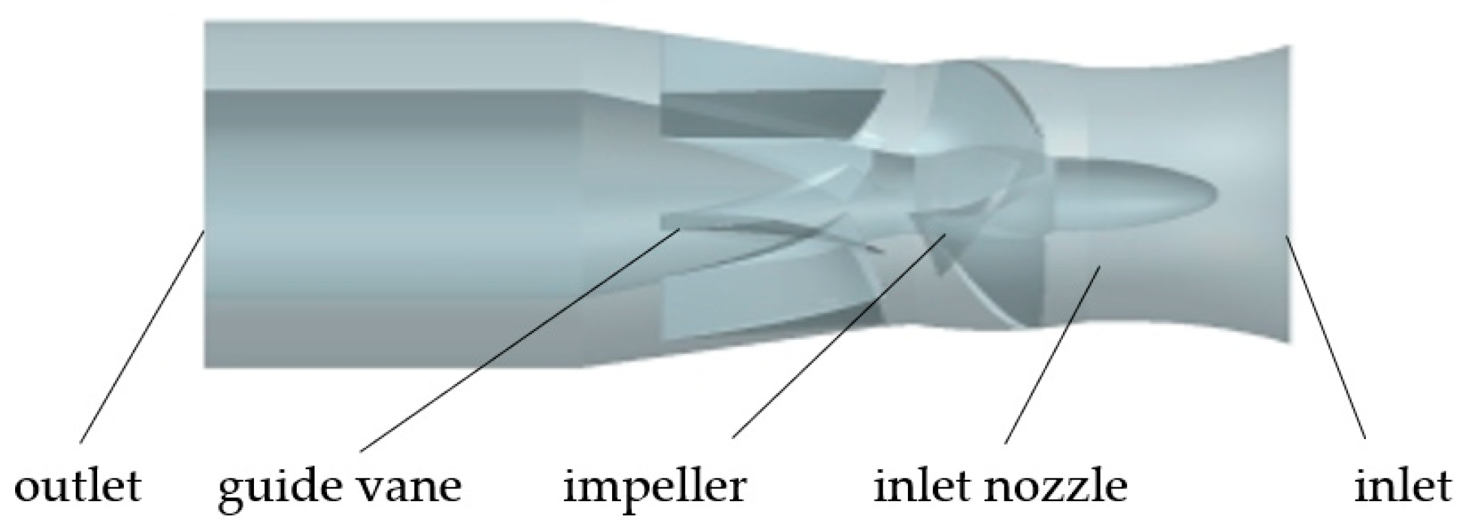
In this paper, the submersible axial flow pump with the specific speed higher than 1250 m0.75/s1.5 is taken as the research object. This kind of pump is mainly used for urban water supplying, drainage, flood controlling, municipal engineering, and water conservancy projects, etc. Considering the requirement of anti-winding, the blades of the impeller are relatively short, the flow ability between the blades is stronger, and the efficiency is lower compared to those of the conventional axial flow pumps. The hydraulic model of whole flow fields includes inlet nozzle, impeller, guide vane and the outlet section. The design flow rate Qopt was 1050 m3/h, head Hopt was 5 m, rotating speed was 1450 r/min, the impeller diameter was 300 mm, hub ratio was 0.35, the number of impeller blades and guide vane blades was three and seven respectively, the axial distance between the impeller outlet with the guide vane inlet was 32 mm, and the axial length of the guide vane was 190 mm. The physical model is shown in Figure 1; water flows from the inlet nozzle to the impeller, then flows into the guide vane, and finally flows out.
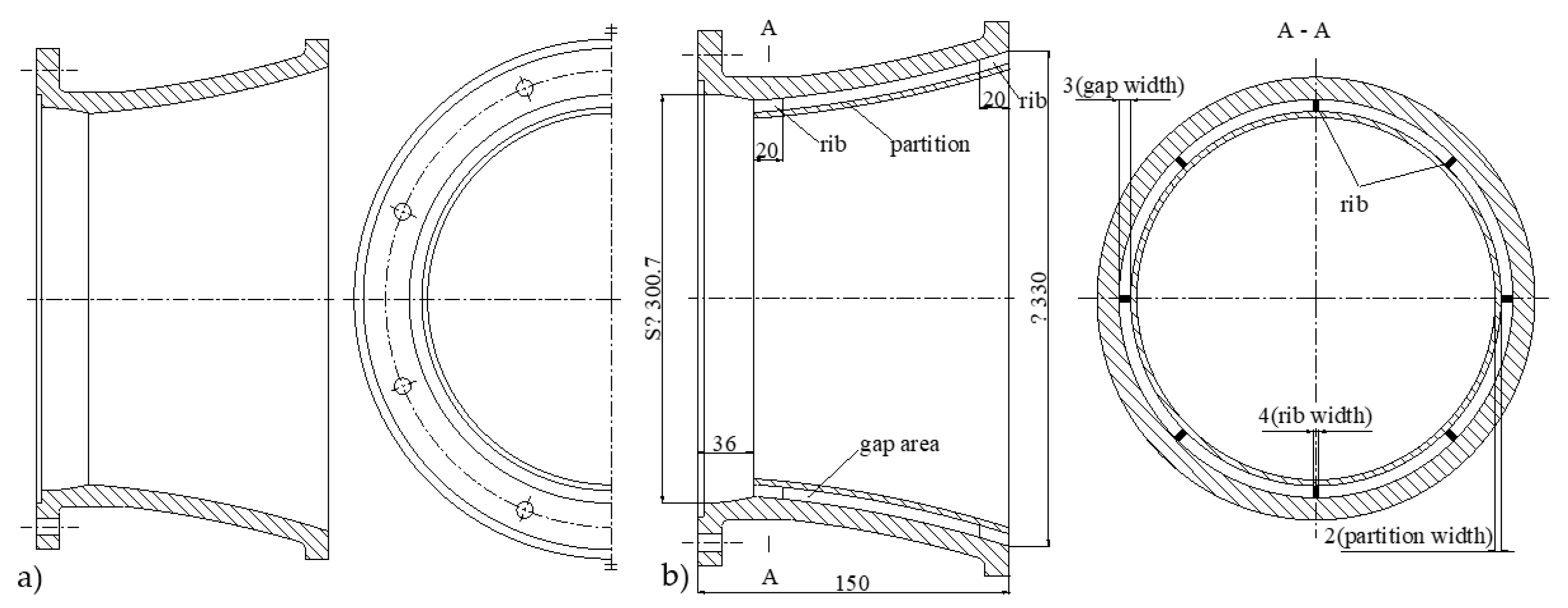
Figure 2 shows the conventional single inlet nozzle and the optimization scheme of the double inlet nozzle. The inner wall of the original nozzle inlet is connected with the partition board by evenly distributing 16 ribs, and the double inlet nozzle is composed of the original nozzle and the partition board. The diameter of the inlet was 330 mm, and the nozzle length was 150 mm, gap width was 3 mm, partition thickness was 2 mm, length of ribs was 20 mm, and ribs width was 4 mm.
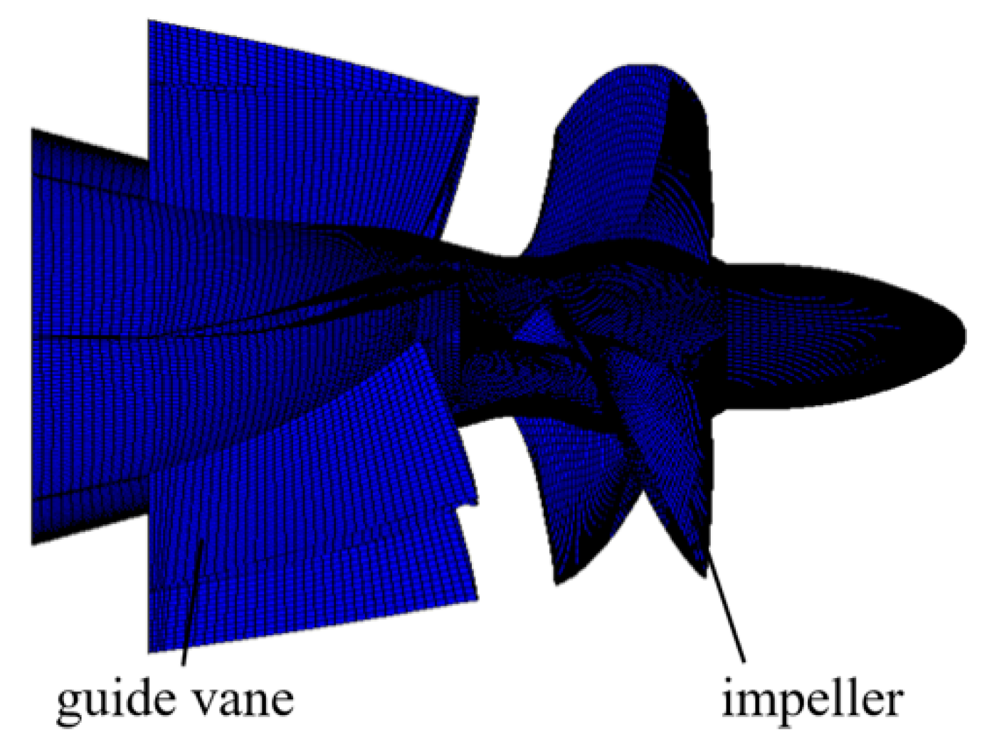
The calculation area was meshed with full hexahedron grid, J-topology was selected for highly warped impeller blades, and H-topology was used for the guide vane. In order to control the distribution of the boundary layer near the blades wall, the blades were surrounded by O-type topology. The meshes are shown in Figure 3.
2.2. Calculation Methods and Boundary Conditions
The commercial Computational Fluid Dynamics (CFD) software ANSYS CFX 15.0 (ANSYS Inc., Pittsburgh, PA, USA) was used to solve the internal Reynolds averaged equations of the axial flow pump. The finite volume method was used to discretize the governing equations. The convection terms were discretized by the two-order upwind difference scheme, and the fully implicit multi-grid coupling solution technique was used. The medium of the pump was water, which is regarded as incompressible fluid. The prediction accuracy of flow field has a complex relationship with grid layout, geometric model, wall function, discrete accuracy, etc. Since its proposal by Lauder and Spalding in 1972, the k-ε turbulence model has been widely used in various turbulence simulation for its simple feature, good calculation stability, and high calculation efficiency, and it is one of widely used models in the field of pump stations to study multi-objective optimization and transient flows in axial flow pumps [21,22,23]. Therefore, the standard k-ε turbulence mode was also adopted in this paper. In order to reduce the influence of the grids number on the accuracy of the calculation results, the head and hydraulic efficiency at the design flow rate of 1.0 Qopt were observed as an indicator to verify the grids independence. When the number of grid nodes is above 1.1 million, the fluctuation of head or hydraulic efficiency is small. Considering the configuration and calculation times of the computer, the final total number of grid nodes selected was 1.3 million. The average y+ of the near wall meshes in whole calculation area was less than 100, and the average y+ on impeller blades pressure and suction sides was less than 50. The inlet was adopted as the static pressure boundary condition, the outlet was adopted as the mass flow boundary condition, the solid walls were set as non-slip and adiabatic wall surface conditions, the standard wall function was adopted on the near wall surface, and the roughness of main flow passage components, such as the impeller and guide vane, was set to 0.025 mm. The water in the impeller was set as the rotating area, while the rest water body was set as the static area. The coupling interfaces between the rotating areas and the static areas were set as transient frozen rotor mode, and the coupling interfaces between the static regions was set as none. The convergence precision was set to be 10−4.
2.3. Test Process
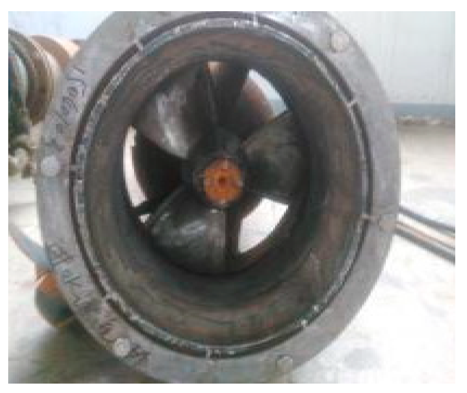
The double inlet nozzle was produced, and the external characteristics of the axial flow pump were tested. The double inlet nozzle is shown in Figure 4.
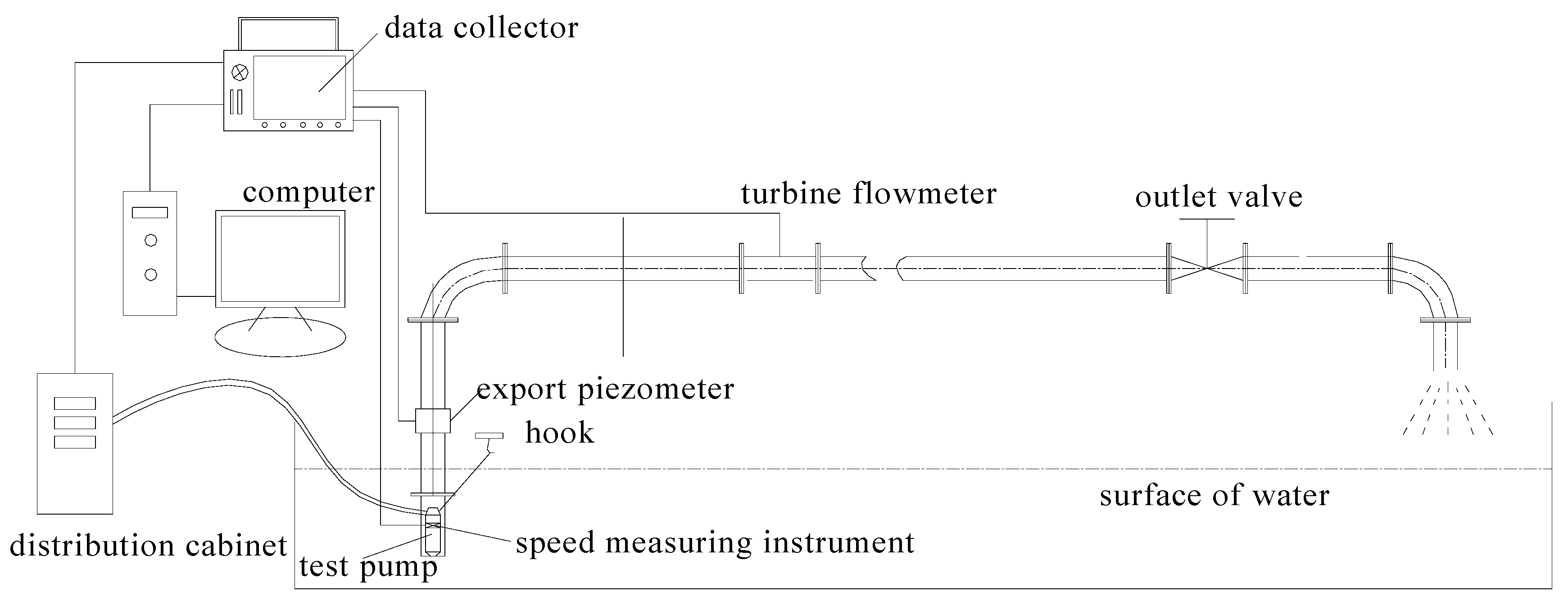
The external characteristic tests were carried out on an open test bench system, and the test bench system precision reached international Class B(ISO 9906:1999, Geneva, Switzerland). The external characteristic test bench system mainly includes the pressure transmitter, the turbine flowmeter, the rotating speed sensor, the power measuring instrument, and the external characteristic data acquisition instrument, etc. Test devices are shown in Figure 5. The WT2000 series pressure transmitter (Welltech Industrial Automation Co., Ltd, Shanghai, China) was adopted, the measuring range was 0–1.0 Mpa, and the precision level was 0.2%. The LWGY300 type turbine(Shangyi group, Shanghai, China) flowmeter with the precision 0.5% was adopted in the experiment. The precision level of the current and voltage sensors was 0.5%, and the HSJ-2010 type hydraulic mechanical (Huazhong University of science and technology, Wuhan, China) comprehensive test instrument was used whose precision level was 0.2%.
2.4. Test Uncertainty Analysis
During the pump performance test, the uncertainty of the system is mainly related to the accuracy and measurement methods of instruments. It is very important to analyze and master the measurement uncertainty of performance indicators such as efficiency, flow rate, and head. The flow rate, torque, and rotating speed can be obtained directly from the sensors’ datum, so the system uncertainty is obtained directly from instruments parameters. The uncertainty of pump efficiency needs to be calculated by the synthesis formula. The system uncertainty of each sub-item is calculated by the systematic error of measuring instruments. The stochastic uncertainty is determined by the analysis and calculation of ten measurements. Comprehensive tests and calculations determined that, when measuring the corresponding type of axial flow pump within the measurements parameters of the test bench, the measurement uncertainty of the pump efficiency was about 0.56%, the measurement uncertainty of the flow rate was about 0.43%, and the measurement uncertainty of the head was about 0.38%. In general, measurement accuracies are high.
3. Calculation Results and Analysis
3.1. Hydraulic Performance Comparison and Analysis
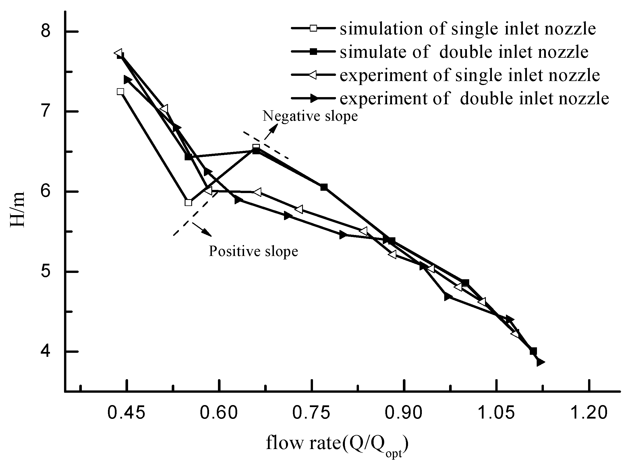
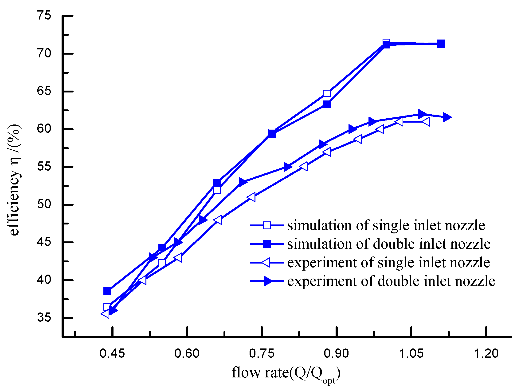
For single inlet nozzle and double inlet nozzle schemes, the head and efficiency of the steady calculations at different flow rates were compared with those of the experimental results. As shown in Figure 6 and Figure 7, under the design flow rate conditions, the simulation results of single inlet nozzle scheme showed that head was 4.85 m and hydraulic efficiency was 71.46%, meanwhile, the test results showed that head was 4.8 m and efficiency was 60.8%. If the estimated motor efficiency was 87%, the tested pump hydraulic efficiency was about 69.88%. Under the condition of small flow rate, due to the obvious pressure difference between the pressure side and the suction side of the blade tip region, the tip leakage flow occurred at the tip clearance, which collided with the main stream at the inlet and generated a vortex at the leading edge of the impeller, and which lead to the increasing of the hydraulic loss caused by the flow in the impeller, resulting in the external characteristic curve at small flow rates being greatly affected by the leakage amount. Eventually, the simulated head was larger than the experimental head. In the small flow area, the rotating stall and the deterioration of the inflow condition of the axial flow pump were two main factors that lead to the hydraulic instability. When the simulation deviated from the optimal working condition area, the errors between the simulation and experiment data occurred, but on the whole, the errors were small. Under the condition of large flow rate, the cavitation of the axial flow pump occurred during the test, for the cavitation model was not added during the simulation, therefore the efficiency of the simulation under the condition of large flow rate was higher than that from the test. In addition, the error of prototype manufacturing, the accuracy of the test bed, and the limited applicability of turbulence models were all the causes for the errors between the simulated values and experimental values. In general, the comparisons between the experimental and simulated results showed that the simulation results of external characteristics were basically consistent with the trend of test curves, and the numerical calculation results were of good credibility.
For the single inlet nozzle scheme, it can be seen from the simulation results that, when the flow rate was reduced to about 0.66 Qopt, the head dropped obviously, the phenomenon of “positive slope” appeared in the head-flow curve, and the unstable rotating stall happened. On the contrary, when the flow rate was reduced to 0.66 Qopt, although the head of the double inlet nozzle scheme had a slight decline, compared with the original scheme, the double inlet nozzle improved the head and efficiency performance.
3.2. Flow Field Analysis
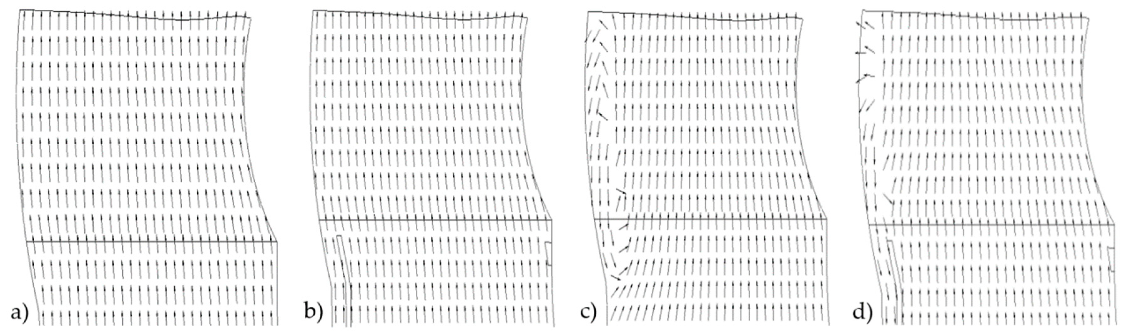
The inlet flow fields at the flow rate of 0.55 Qopt in the saddle region and at the design flow rate of 1.0 Qopt were selected to be compared with each other. Figure 8 shows the inlet axial velocity vectors of the single inlet nozzle scheme and the double inlet nozzle scheme at shaft section plane of crossing one blade center.
Because the axial pump had the swirls and backflows near the edge at the impeller blades inlet, the smaller flow rate was, the larger swirls and backflows strength were, as shown in Figure 8. It can be seen from the Equation (1) of Euler that the head and the pressure were of course influenced by the swirls and backflows near the edge at the impeller blades inlet; these are also the reasons that the change happens on performances for different inlet nozzles.
where, Ht is the theoretical head, m; u2 is the edge rotating velocity at impeller blade outlet, m/s; vu2 is the fluid circumferential speed at impeller blade outlet, m/s; u1 is the edge rotating velocity at impeller blade inlet, m/s; vu1 is the fluid circumferential speed at impeller blade inlet, m/s; and g is the acceleration of gravity, m/s2.
When flow rate was less than 1.0 Qopt, the head and the pressure on the pressure side of the impeller blades were large; swirls flowing from the pressure side to the suction side at the position of inlet edge of the impeller blade happened; swirl flow forms positive circumferential speed vu1, if vu1 was large at some flow rates, theoretical head decreases; and the phenomenon of “positive slope” appeared in the flow-head curve. However, if the double inlet nozzle scheme is adopted, swirls flow will be resisted due to the ribs; normally, swirl flow happens strongly at the rim of the impeller, thus circumferential speed vu1 is very small if the ribs exist, and the theoretical head will be influenced only a little by the swirls.
It can be seen from Figure 8a and Figure 8b that, at the flow rate of 1.0 Qopt, well distributed liquid flowed into the impeller chamber through the gap region and inlet nozzle not only in the scheme of the single inlet nozzle, but in the scheme of the double inlet nozzle. With the decreasing of the flow rate, the phenomenon of rotating stall occurred at the flow rate of 0.55 Qopt. It can be seen from Figure 8c that, there were swirls and backflows near the rim under the single inlet nozzle condition, and that swirls and backflows blocked the inlet channel and reduced the effective flow area in the pump, affecting the performance of the pump. For the double inlet nozzle scheme in Figure 8d, the liquid flowed through the gap region into the impeller chamber, as well as the nozzle entrance. Comparing the two schemes in the saddle zone at the flow rate of 0.55 Qopt, the backflow area in the double inlet nozzle scheme was smaller than that in the single inlet nozzle scheme, therefore the double inlet nozzle scheme had a large mainstream flow area, which resulted in stable operation of the axial pump at small flow rate.
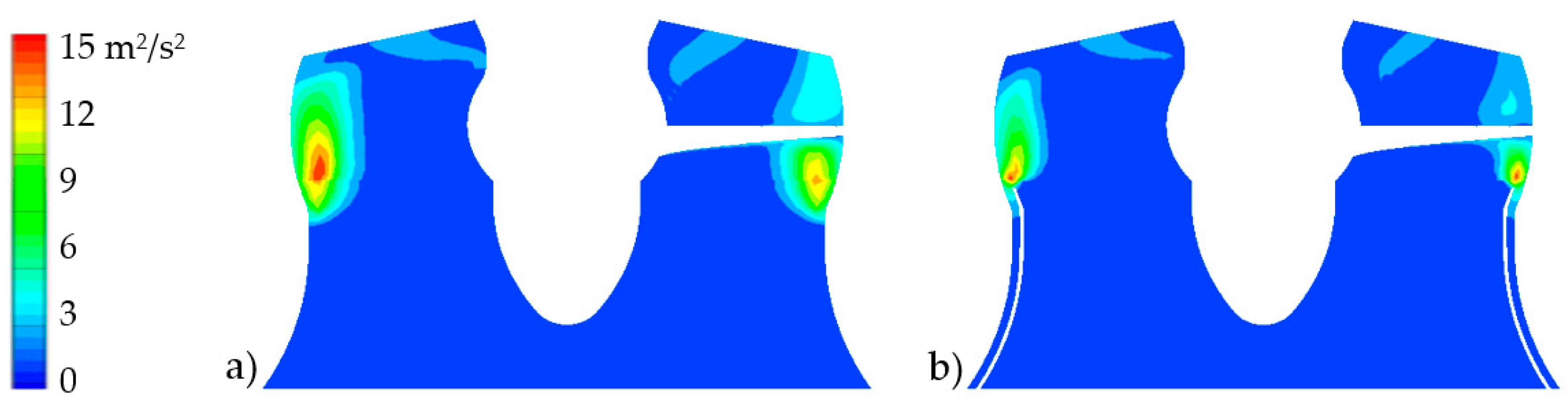
Figure 9 shows the distributions of turbulent kinetic energy in the impeller area and inlet nozzle area at the flow rate of 0.55 Qopt at shaft section plane of crossing one blade center. The turbulent kinetic energy was small not only in the inlet nozzle, but in the impeller chamber near the hub area. At the outer edge of the impeller, especially at the junction between the inlet and the impeller, the turbulent energy was large and the flow was disordered, leading to energy loss.
Comparing the two schemes, it was found that the region with larger turbulent kinetic energy in the double inlet nozzle scheme was obviously smaller than that in the single inlet nozzle scheme. The swirls in the double inlet nozzle scheme were weak and the flow was more stable, therefore the hydraulic loss in the double inlet nozzle scheme was relative small.
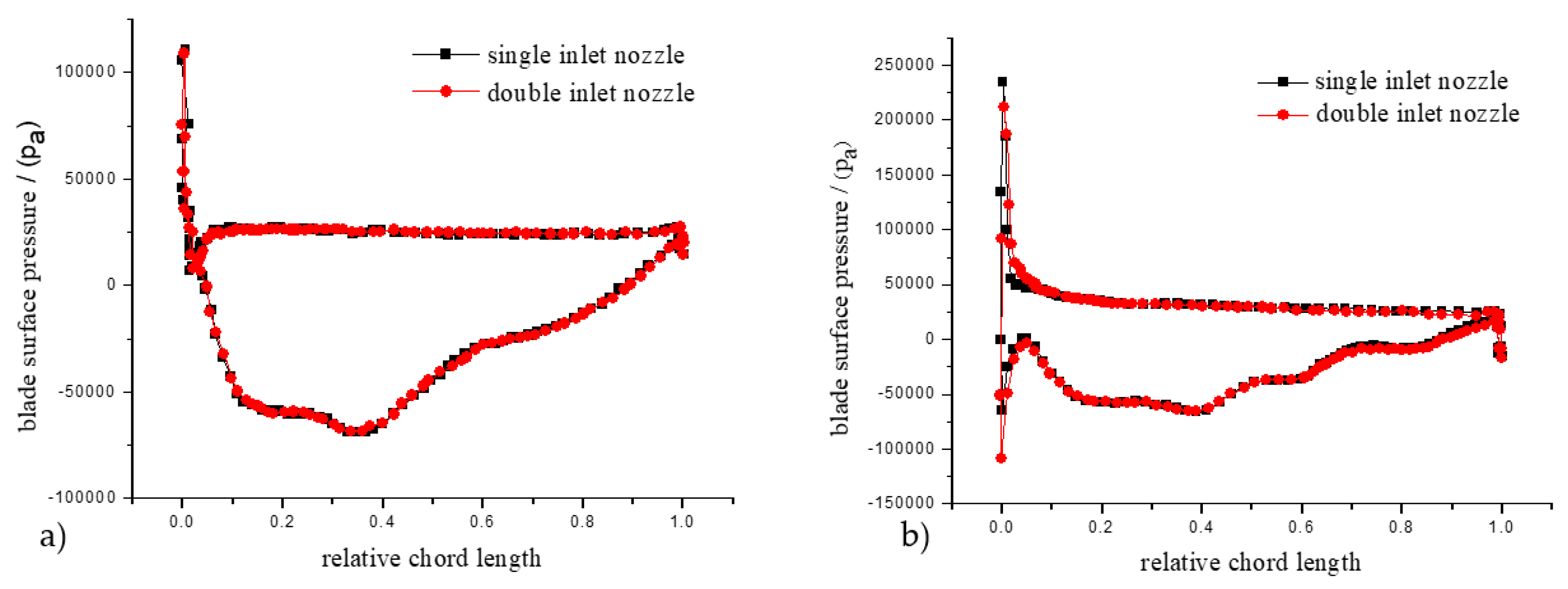
Figure 10 shows the distributions of the static pressure on impeller blade pressure and suction sides at the radius of 35 mm and 67 mm and at the flow rate of 0.55 Qopt and 1.0 Qopt (the radius 35 mm and the radius 67 mm are the radius from the hub to the rim, respectively). The abscissa is the ratio of the length of the projection between the points in the blade cross section from the leading edge in the chord-wise direction to the chord length of the blade section. It can be seen from Figure 10a and Figure 10b that, at the flow rate of 1.0 Qopt, there was no obvious difference between the single inlet nozzle scheme and the double inlet nozzle scheme. When the flow rate was reduced to 0.55 Qopt, the pressure on the blade pressure side of the double nozzle scheme reduced near the leading edge of the blade, while the pressure increased a little near the outlet of the blade, as shown in Figure 10c at the radial position of 35 mm. Also shown in Figure 10d, the distributions of the static pressure on the blade pressure side were almost the same at the radial of 67 mm for the two schemes. However, the pressure on the blade suction side of the double inlet nozzle scheme was obviously smaller than that of the single inlet nozzle scheme. As the pressure difference between pressure side and suction side of the impeller increased, the head of the pump rose. In general, at the design flow rate, pressure did not show an obvious difference between the single inlet nozzle scheme with double inlet nozzle scheme. When the flow rate decreased to the saddle zone, the difference became obviously.
3.3. Performance Comparison
In order to compare the influences of different double nozzle gap widths on the performance of the axial flow pump, double inlet nozzles with gap widths of 2 mm and 4 mm were designed, with either the similar grids or boundary conditions being used to simulate performances. Table 1 lists four schemes structure parameters including the single inlet nozzle.
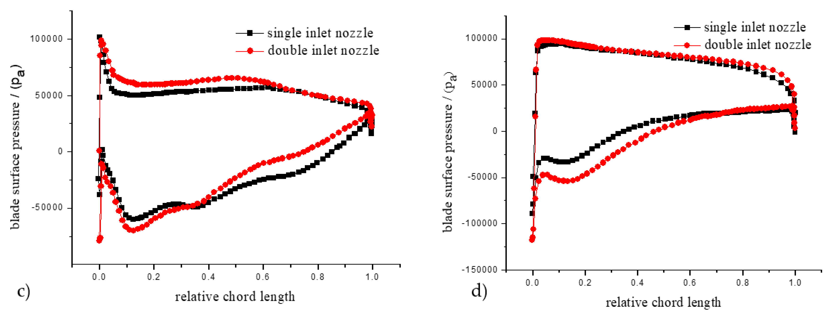
Figure 11a shows simulation results. When the flow rate exceeded 0.65 Qopt, head curves of four schemes were similar, and head values were almost the same. However, when the flow rate was less than 0.65 Qopt, the differences between four schemes were large. Although the effects of three double inlet nozzles schemes on head performance curves were not the same in the small flow area, head-flow curves of three double inlet nozzles schemes were obviously better than that of the single inlet nozzles scheme, which indicates that double inlet nozzles schemes can improve the operation instability of the axial flow pump in the saddle zone. The No.2 scheme showed the least head drop and the best optimization effect, while the No.3 scheme was the worst. These results indicate that the gap width of the double inlet nozzle is an important factor affecting the performance of the axial flow pump. Figure 11b shows the effect of different double inlet nozzles on efficiency performance curve under the condition of small flow rate. All efficiency curves of double inlet nozzle schemes were slightly higher than that of the single inlet nozzles scheme by about 2%. When the flow rate was close to 1.0 Qopt, the differences were not obvious, and in small flow rate area, the No.2 scheme seemed to make the greatest contribution to the efficiency improvement.
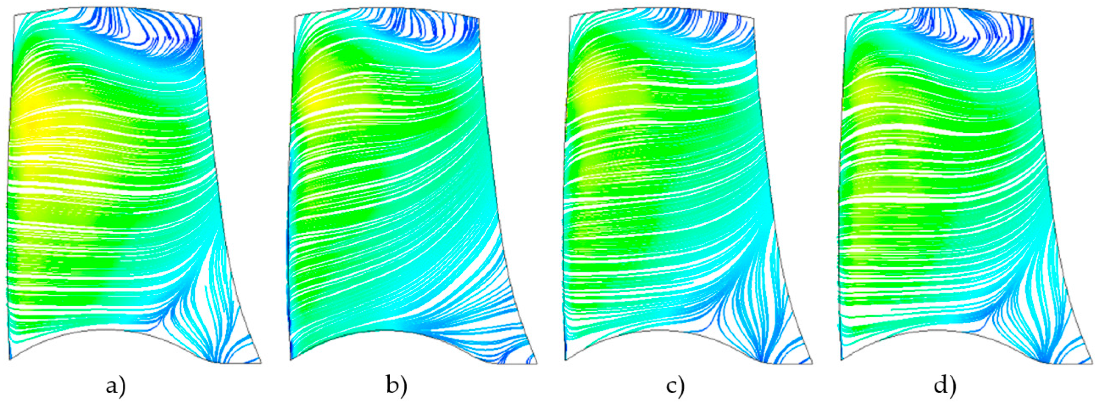
Figure 12 represents streamlines on blade suction sides of the four different nozzles at the flow rate of 0.55 Qopt. There was turbulence and significant separated flow on the hub side and the rim side in the vicinity of the exit. The size of the backflow range was similar near the hub and there was no obvious improvement with the double inlet nozzles. Near the side of the rim, the largest range of backflow existed in the single inlet nozzle scheme and No.3 scheme, and the most obvious improvement on the fluid backflow was in the scheme of No.2. This was most clearly consistent with the improvement of the head-flow curve saddle zone with the scheme of No.2. According to the comparison, it can be noted that the No.2 double inlet nozzle with reasonable inlet gap width can eliminate the saddle area of head-flow curve better on small flow condition and improve the hydraulic performance of axial flow pump obviously.
4. Simulation of Different Specific Speed Axial Pump
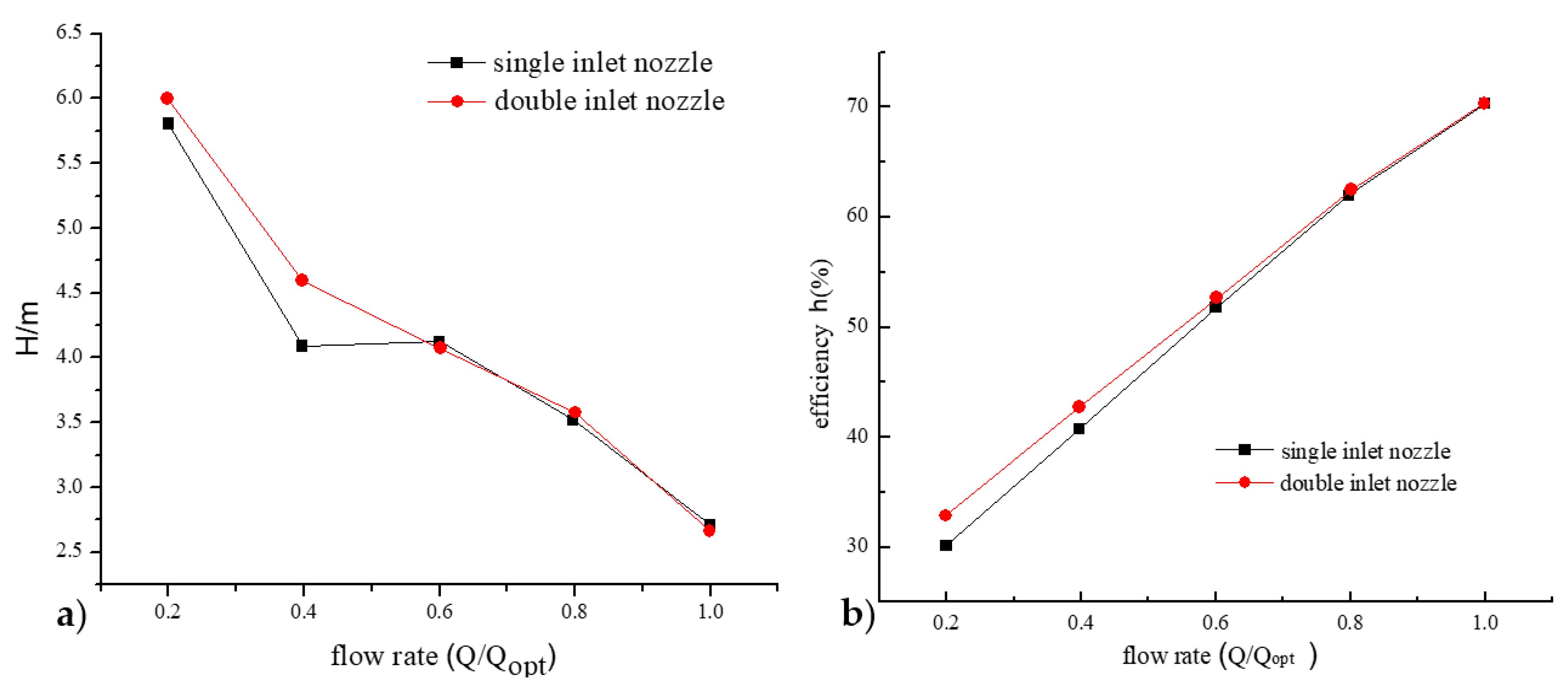
In order to test the improvement effects of double inlet nozzle scheme on the saddle-shape performance of another axial flow pump, an axial flow pump with specific speed of ns = 700 m0.75/s1.5 was numerically simulated; the design flow rate Qopt was 700 m3/h, head Hopt was 2.5 m, and rotating speed was 980 r/min. The structure of the double nozzle was the same as the previous one, the gap width was 3 mm, and the partition thickness was 2 mm. It can be seen from the head-flow curve of Figure 13a that the head of the double inlet nozzle scheme was similar to that of the single inlet nozzle scheme in the stable working area, while in small flow rate area where the saddle-shape zone appears easily, the head-flow curve of the double inlet nozzle scheme changed more smoothly. Therefore, the double inlet nozzle scheme can also effectively improve the saddle area of the axial flow pump with specific speed of ns = 700 m0.75/s1.5. Figure 13b shows similar characteristics as those shown in Figure 11b, such that the efficiency curve of the double inlet nozzle scheme was slightly higher than that of the single inlet nozzle by about 2%.
5. Conclusions
When axial flow pumps run in saddle areas, they may produce violent vibrations and noise, and their effective heads and operation stabilities decrease. The results of this study show that the double inlet nozzle scheme has no obvious effect on the head of the axial pump at relatively large flow rates, while at small flow rate where the saddle-shape zone appears easily, the head-flow curve of double inlet nozzle scheme changes smoothly. The region with larger turbulent kinetic energy in the double inlet nozzle scheme is obviously smaller than that in the single inlet nozzle scheme. At the design flow rate of 1.0 Qopt, pressure distribution does not show obvious difference between the single and double inlet nozzle schemes. However, when the flow rate decreases to 0.55 Qopt, pressure distribution differences becomes obviously. The gap width of the double inlet nozzle is an important factor affecting the pump performance curve and streamline on the blade suction sides. The No.2 double inlet nozzle scheme shows the least head drop and the best optimization effect in different axial pumps.
Author Contributions
W.C. designed and tested the scheme, performed simulations, and organized the paper. W.L. helped to analyze the data. All authors have read and agreed to the published version of the manuscript.
Funding
This work was supported by the National Key R&D Program of China (2018YFC0810506) and the Key R&D Program of Zhenjiang (SH2017049).
Conflicts of Interest
The authors declared no potential conflicts of interest with respect to the research, authorship, and/or publication of this article.
References
- Shi, L.; Tang, F.; Zhou, H. Axial-flow pump hydraulic analysis and experiment under different swept-angles of guide vane. J. Trans. Chin. Soc. Agric. Eng. 2015, 31, 90–95. [Google Scholar]
- Zheng, Y.; Mao, Y.; Zhou, D. Flow characteristics of low-lift and large flow rate pump installation in saddle zone. J. Drain. Irrig. Mach. Eng. 2011, 5, 369–373. [Google Scholar]
- Pan, Z.; Li, J.; Li, X. Performance curve instability and rotating stall. J. Trans. Chin. Soc. Agric. Mach. 2012, 5, 64–69. [Google Scholar]
- Pan, Z.Y.; Li, J.J.; Li, H.; Liu, W. Overview for research on rotating stall pump. J. Fluid Mach. 2011, 2, 35–40. [Google Scholar]
- Shibata, A.; Hiramatsu, H.; Komaki, S. Study of flow instability in off design operation of a multistage centrifugal pump. J. Mech. Sci. Technol. 2016, 2, 493–498. [Google Scholar] [CrossRef]
- Greitzer, E.M.; Nikkannen, J.; Phanddad, D.E. A fundamental criterion for the application of rotor casing treatment. J. Fluids. Eng. 1979, 2, 237–243. [Google Scholar] [CrossRef]
- Goltz, I.; Kosyna, G.; Wulff, D. Part load operating performance and stall inception of a single-stage axial-flow pump C. In Proceedings of the 10th International Symposium on Transport Phenomena and Dynamics of Rotating Machinery, Honolulu, HI, USA, 7–11 March 2004; pp. 1–8. [Google Scholar]
- Kosyna, G.; Goltz, I.; Stark, U. Flow structure of an axial-flow pump from stable operation to deep stall C. In Proceedings of the 1st Fluids Engineering Division Summer Meeting (ASME 2005), New York, NY, USA, 7–11 July 2005; pp. 1389–1396. [Google Scholar]
- Shi, W.; Shao, P.; Zhang, D. Numerical simulations and PIV experiment of flow field in axial flow pump. J. Drain. Irrig. Mach. Eng. 2015, 4, 277–282. [Google Scholar]
- Kurokawa, J. J-groove technique for suppressing various anomalous flow phenomena in turbo machines. Int. J. Fluid Mach. Syst. 2010, 4, 1–13. [Google Scholar]
- Pacot, O.; Kato, C.; Guo, Y. Large eddy simulation of the rotating stall in a pump-turbine operated in pumping mode at a part-load condition. J. Fluids Eng. 2016, 11, 111102. [Google Scholar] [CrossRef]
- Yang, H.; Sun, D.; Tang, F. Experiment research on inlet flow field for axial-flow pump at unsteady operating condition. J. Drain. Irrig. Mach. Eng. 2011, 5, 406–420. [Google Scholar]
- Chen, W.; Lu, L.; Wang, G. Influence of axial-flow pump operating condition on the pre-swirl at impeller chamber inlet. J. Hydroelectr. Eng. 2012, 1, 213–219. [Google Scholar]
- Zhang, R.; Chen, H.-x. Study on the improvement of hydrodynamic performance of axial-flow pump at stall condition. J. Hydroelectr. Eng. 2014, 3, 292–300. [Google Scholar]
- Wang, L.; Shi, W.; Shen, C.; Xu, L. Numerical analysis and prediction of hydraulic performance of vertical axial-flow pump system model. J. Drain. Irrig. Mach. Eng. 2016, 9, 776–782. [Google Scholar]
- Dai, C.-c.; Guo, P.-c.; Luo, X.-q. Numerical analysis of tip clearance flow characteristic in axial-flow pump. J. Fluid Mach. 2009, 6, 32–35. [Google Scholar]
- Wang, M.; Li, Y.; Yuan, S.; Meng, F. Runaway characteristics of two-way passage axial-flow pump installation. J. Drain. Irrig. Mach. Eng. 2018, 5, 384–390. [Google Scholar]
- He, N.; Tan, M.; Liu, H.; Hung, X. Test and analysis on pressure pulsation and hydraulic performance of saddle zone in axial flow pump. J. Drain. Irrig. Mach. Eng. 2018, 2, 118–123. [Google Scholar]
- Zhang, D.; Wu, S.; Shi, W.; Pan, D. Application and experiment of different turbulence models for simulating tip leakage vortex in axial-flow pump. J. Trans. Chin. Soc. Agric. Eng. 2013, 13, 46–53. [Google Scholar]
- Zheng, Y.; Chen, Y.; Zang, R.; Ge, X. Analysis on unsteady stall flow characteristics of axial-flow pump. J. Transact. Chin. Soc. Agric. Mach. 2017, 7, 127–135. [Google Scholar]
- Wang, F.; Tang, X.; Chen, X.; Xiao, R. A review on flow analysis method for pumping stations. J. Hydraul. Eng. 2018, 1, 47–61, 71. [Google Scholar]
- Zheng, Y.; Sun, A.; Yang, C.; Jiang, W. Multi-objective Optimization Design and Test of Axial-flow pump. J. Trans. Chin. Soc. Agric. Mach. 2017, 9, 129–136. [Google Scholar]
- Ramadhan, A.; Al-Obaidi, A.R.; Mohammed, A.A. Numerical Investigations of Transient Flow Characteristic in Axial Flow Pump and Pressure Fluctuation Analysis Based on the CFD Technique. J. Eng. Sci. Tech. Rev. 2019, 6, 70–79. [Google Scholar]
Figure 1.
Physical model of the axial flow pump.

Figure 2.
Structure of inlet nozzle: (a) single inlet nozzle and (b) double inlet nozzle.

Figure 3.
Structured meshes.

Figure 4.
The double inlet nozzle.

Figure 5.
Open test system.

Figure 6.
Comparison of head-flow curves.

Figure 7.
Comparison of efficiency-flow curves.

Figure 8.
Velocity in the inlet sections at different flow rate: (a) single inlet nozzle (1.0 Qopt); (b) double inlet nozzle (1.0 Qopt); (c) single inlet nozzle (0.55 Qopt) and (d) double inlet nozzle (0.55 Qopt).
Figure 8.
Velocity in the inlet sections at different flow rate: (a) single inlet nozzle (1.0 Qopt); (b) double inlet nozzle (1.0 Qopt); (c) single inlet nozzle (0.55 Qopt) and (d) double inlet nozzle (0.55 Qopt).

Figure 9.
The distribution of turbulent kinetic energy: (a) single inlet nozzle and (b) double inlet nozzle.
Figure 9.
The distribution of turbulent kinetic energy: (a) single inlet nozzle and (b) double inlet nozzle.

Figure 10.
The static pressure on blade surfaces: (a) radius of 35 mm(1.0 Qopt); (b) radius of 67 mm (1.0 Qopt); (c) radius of 35 mm( 0.55 Qopt); (d) radius of 67 mm( 0.55 Qopt).
Figure 10.
The static pressure on blade surfaces: (a) radius of 35 mm(1.0 Qopt); (b) radius of 67 mm (1.0 Qopt); (c) radius of 35 mm( 0.55 Qopt); (d) radius of 67 mm( 0.55 Qopt).


Figure 11.
Performance of different double inlet nozzles: (a) head-flow curves and (b) efficiency-flow curves.
Figure 11.
Performance of different double inlet nozzles: (a) head-flow curves and (b) efficiency-flow curves.

Figure 12.
Streamlines at the suction sides: (a) Single inlet nozzle; (b) No. 1 double inlet nozzle; (c) No. 2 double inlet nozzle and (d) No. 3 double inlet nozzle.
Figure 12.
Streamlines at the suction sides: (a) Single inlet nozzle; (b) No. 1 double inlet nozzle; (c) No. 2 double inlet nozzle and (d) No. 3 double inlet nozzle.

Figure 13.
Performance of axial-flow pump with specific speed of 700 m0.75/s1.5: (a) head-flow curves and (b) efficiency-flow curves.
Figure 13.
Performance of axial-flow pump with specific speed of 700 m0.75/s1.5: (a) head-flow curves and (b) efficiency-flow curves.


Table 1.
Structure parameters of the double inlet nozzle.
| Inlet Nozzle | Gap Width (mm) | Partition Thickness (mm) |
|---|---|---|
| single inlet nozzle | 0 | 0 |
| No.1 double inlet nozzle | 2 | 2 |
| No.2 double inlet nozzle | 3 | 2 |
| No.3 double inlet nozzle | 4 | 2 |
© 2020 by the authors. Licensee MDPI, Basel, Switzerland. This article is an open access article distributed under the terms and conditions of the Creative Commons Attribution (CC BY) license (http://creativecommons.org/licenses/by/4.0/).
Share and Cite
MDPI and ACS Style
Cao, W.; Li, W. Study on the Performance Improvement of Axial Flow Pump’s Saddle Zone by Using a Double Inlet Nozzle. Water 2020, 12, 1493. https://doi.org/10.3390/w12051493
AMA Style
Cao W, Li W. Study on the Performance Improvement of Axial Flow Pump’s Saddle Zone by Using a Double Inlet Nozzle. Water. 2020; 12(5):1493. https://doi.org/10.3390/w12051493
Chicago/Turabian StyleCao, Weidong, and Wei Li. 2020. "Study on the Performance Improvement of Axial Flow Pump’s Saddle Zone by Using a Double Inlet Nozzle" Water 12, no. 5: 1493. https://doi.org/10.3390/w12051493
Note that from the first issue of 2016, this journal uses article numbers instead of page numbers. See further details here.