Numerical Simulation of Frost Heave of Concrete Lining Trapezoidal Channel Under an Open System


College of Water Resource and Architectural Engineering, Northwest A&F University, Yangling 712100, China
*
Author to whom correspondence should be addressed.
Water 2020, 12(2), 335; https://doi.org/10.3390/w12020335
Submission received: 10 December 2019
/
Revised: 17 January 2020
/
Accepted: 21 January 2020
/
Published: 23 January 2020
(This article belongs to the Section Water Use and Scarcity)
Abstract
:To study the distribution law of frost heave in base soil with a concrete lining structure and compound geomembrane, the coupled heat–moisture–stress, capillary action, and membrane water migration were considered, and multi-field coupling software was used to simulate the frost heaving of the channel. A 67-day frost heaving process of the foundation soil considering the change of groundwater level around a channel was also considered. The displacement fields at different positions on the base soil were obtained. The results showed that the frost heave was the largest at about one-third of the slope from the bottom of the channel, and the maximum is 8.243 cm. A compound geomembrane on the lower side of the lining can reduce the frost heaving of the foundation soil to some extent, and the maximum normal displacements of the lining along the slope and at the top of the channel decreased by 14.3% and 15.5% after adding the compound geomembrane.
1. Introduction
Frozen soil is mainly distributed in the northern hemisphere. Permafrost accounts for about 23% of the global land area, and seasonally frozen soil is more widely distributed. Frozen soil is widely distributed in most areas of North America, Europe, and Asia. Some countries, such as Russia, the United States, and Canada, cover large areas of permafrost. In China, permafrost accounts for about 21.5% of the country’s land areas, and seasonally frozen soil accounts for about 53.5% of the country’s land area [1]. In the seasonally frozen soil area, a frozen-melting layer is generally present in the surface layer. When this layer is used as a building foundation, the freezing and melting process directly affects the safety and stability of the upper building [2].
When the temperature decreases, the upheaval and displacement of soil will appear during the process of soil freezing. This is a problem in many permafrost regions, which can cause damage to foundations, such as foundation walls, pillars, and so on. Therefore, many countries have conducted a lot of experiments about it, such as Russia and the United States. In channel engineering, concrete channel linings for antiseepage can greatly reduce channel leakage losses, and they are the most widely used water-saving engineering technological measure in China [3]. In most parts of northern China, a large number of hydraulic channel structures are very sensitive to frost heaving due to factors, such as their small thicknesses and low weights [4]. In the shallow depth of the groundwater, the channel section produces strong frost heaving, called open system trapezoidal channel frost heaving. In the winter, the moisture, temperature, and stress fields interact with the base soil, producing an uneven frost heave [5,6]. This affects the channel lining, causing cracking and leakage of the lining, directly affecting its normal operation. This is the most common form of freezing damage in channel irrigation projects. Frost heaving damage of concrete lining channels in the cold regions of northern China is very severe and frequent. China has invested considerable funding towards the maintenance and repair of channels every year. Therefore, the mechanism and prevention measures for the frost heaving damage of the channels must be studied. This will have significant societal and economic benefits and practical significance for irrigation district construction, food security, and economic development.
The theory of multi field coupling has been developed in recent years. Li et al. [7] built a numerical heat–water–mechanics model based on energy, mass, and momentum conservation principles and then carried out an experiment in order to explain the heat–water–mechanics interaction mechanism of the freezing soil. Bai et al. [8] conducted a series of one-side freezing experiments to illustrate moisture migration and frost heave mechanisms. He et al. [9] established a coupled model for liquid water–vapor–heat migration, in which the phase changes of vapor–liquid and water–ice were considered. In the past, research on the three-field coupling model mostly concentrated on subgrade engineering, and channel engineering was examined less frequently [10,11,12,13]. Li et al. [14] established a two-dimensional hydrothermal conduction model to analyze the difference between new and traditional channel linings. Li et al. [15] established a hydro-thermal coupling model to simulate freezing in the melting cycle and found that the maximum frost heave occurred at the toe of the channel slope. Liu et al. [16] added an equivalent heat capacity of the heat of fusion to the heat conduction equation based on the Clapeyron equation and Darcy’s law using three-field coupling software. Wang et al. [17] simulated the displacement and stress fields of frost heave for 30 different lining channels based on three-field coupling theory, revealing the size effect of lining frost heaving damage. Previously, a constant temperature layer was used only for the lower boundary of the model. In this study, the impact of groundwater-level changes on the temperature field was examined, and a dynamic temperature lower temperature boundary was used. When calculating the water driving force, capillary action and membrane water migration theory were considered simultaneously, and the process of frost heave growth of the canal-based frozen soil was simulated.
2. Frost Heave Model and Analysis Method
The water, temperature, and displacement fields of the channel foundation are coupled during the frost heaving process. The change in the temperature field causes the water in the unfrozen zone to migrate to the freezing front, and the large heat of fusion affects the distribution of the temperature field. The moisture migrates due to the temperature gradients, and the formation of ice lenses hinders the migration of water. Under the joint action of the temperature and water fields, the thermal conductivity, heat capacity, density, and void ratio of the channel soil change, and the displacement field changes due to the freezing water. The temperature field, water field, and stress field can all be expressed by partial differential equations. The three partial differential equations can be solved simultaneously by COMSOL to simulate the frost heaving process of channel foundation soil.
2.1. Basic Assumption
Combining existing research results and engineering practices and for ease of analysis, the following assumptions were made.
- (1)
- The concrete lining is an isotropic material.
- (2)
- Since the dimension of the lining channel along the water delivery direction is much larger than the cross-sectional area and the cross-section is symmetric, the lining force in the water conveyance direction and the heat conduction process of the channel base do not change. Thus, the analysis of the expansion failure can be simplified to a plane strain problem [18].
- (3)
- The heat transported by the migration of moisture to the frozen zone is negligible.
- (4)
- There is no overlying load above the foundation of the channel, and the ice pressure is 0.
2.2. Heat Conduction Equation
During the heat transfer process in the base soil, the convective heat transfer is small and can be ignored [19]. The transient heat conduction process in the base soil satisfies the following partial differential equation:
where is the density of the soil, is the volume heat capacity, T is the temperature, t is the time, y is the vertical direction coordinate, x is the horizontal direction coordinate, L is the water heat of fusion, is the thermal conductivity of the material, is the volume content of the ice, and is the density of ice.
2.3. Moisture Transfer Equation
In this study, the Richard equation model was used to simulate the water migration in unsaturated soil. In the Richards’ equation, the water migration driving force was added in the form of pressure head. The Richards’ equation is as follows:
where is the volume fraction of fluid within the soil, is the volume fraction of in-situ water in soil, is the volume fraction of moisture transfer in soil, is the gradient operator, HP is the pressure head, t is the time, k is the permeability coefficient, and y is the vertical direction coordinate.
The permeability coefficient k can be expressed by the following equation [20]:
where k0 is the unfrozen soil permeability coefficient, y is the vertical direction coordinate, T is the temperature, T0 is the water freezing temperature, β is a test parameter, and is the ice lens position height.
2.4. Moisture Migration Driving Force
At present, there is not a comprehensive and reasonable explanation of the driving force of water migration during the freezing process. The membrane water migration mechanism and capillary action were considered in this study.
The membrane water migration mechanism considers that the soil particles are surrounded by a water film. The frost heaving process in the soil causes an uneven distribution of the water in the film, and the water tends to migrate to the thin film areas. Under certain conditions, the unfrozen water content and temperature are single-valued functions, so it can be assumed that there is a functional relationship between the thickness of the unfrozen water film and the temperature. Konrad and Morgenstern [21] proposed a linear relationship between the temperature gradient and moisture migration flux. Kay and Groenevelt [22] suggested that the temperature-induced moisture migration driving force can be expressed by the Clapeyron equation:
where is the water pressure, is the density of ice, is the density of water, is the pressure head, is the ice pressure, L is the water heat of fusion, T is the temperature, and T0 is the water freezing temperature. Overlying loads on the channel were not considered, and thus, Pi = 0.
In this study, temperature gradients were the main driving force for water migration. For capillary action, the capillary rise height, hc, can be approximated by the following formula [23]:
where C is a coefficient determined by the particle size and surface roughness of the soil particles, which was set to 10 mm2; e is the soil void ratio; and D10 is the effective particle size of the soil particles, and D10 was set to 0.001 mm.
2.5. Stress–Strain Equation
The stress equations for the channel frost heave deformation consist of the differential equations of equilibrium, a geometric equation, and a physical equation, defined as follows.
Differential equations of equilibrium:
Physical equation:
Geometric equation:
Volumetric strain caused by frost heaving of frozen soil when T < 0 °C:
In these equations, is the volume fraction of fluid within the soil, is the density of ice, is the density of water, x and y represent directions, f is a body force, is the normal stress, is the shear stress, is the elasticity modulus, is the Poisson’s ratio, is the initial strain along the x direction, is the initial strain along the y direction, is the initial shear strain, T is the temperature, is the displacement vector, is the coefficient of ice expansion in the base soil, is the angle between and , and is the strain caused by water and temperature.
2.6. Contact Behavior Between Foundation Soil and Concrete
When a compound geomembrane is not present between the concrete and channel soil, there exists a freezing strength between the two. The normal stress is the normal freezing strength, and the tangential stress is the tangential freezing strength. When the concrete and compound geomembrane are used, there is no freezing strength between the two. This is because the compound geomembrane consists of Polyethylene film and geotextile, which is smooth and waterproof, so there definitely will be no freezing strength between the concrete lining and base soil. The tangential stress is the friction between the lining and the foundation soil. Uneven frost heaving causes the two to be exposed to the air separately. Therefore, this gap size was measured and then assumed that there was an 8-mm air film. The presence of the air film hinders the freezing between the foundation soil and the lining and then improves the frost heave adaptability of the lining. Besides, it hinders the conduction of the negative temperature to the base soil to some extent.
3. Finite Element Model Calculation and Parameter Selection
3.1. Channel Prototype
In this study, a numerical simulation of channel frost heave was carried out in the Hangjinhouqi section of the Jiefangsi Irrigation District of Inner Mongolia (Figure 1). The channel is lined with C25 concrete. The soil of the channel base is clay, the soil dry density is 1.39 g/cm3, and the water content is 12% to 15%. The channel is located in the Hetao Irrigation District. It is situated in a seasonally frozen soil area. The temperature drops in the winter and the channel stops running late in the season. This leads to a higher groundwater level, accelerates the water migration and freezing front movement, and finally causes the channel lining to freeze. Frost heaving volume data were measured from 6 December 2017 to 24 February 2018. The measurement points were set at one-third and two-thirds of the slope length from the bottom of the channel. The maximum amount of frost heaving occurred on 10 February 2018. After this, the temperature gradually rose, and the frozen soil melted. The frost heave process from 6 December 2017 to 10 February 2018 was simulated in this study, a period of 67 days.
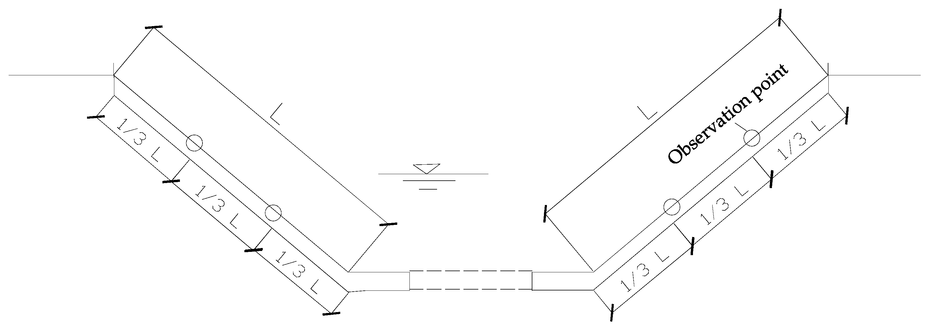
The elevation points were set at positions one-third and two-thirds of the slope distance from the top of the channel, and then the level was used to observe and record elevation changes by using the standard fourth-grade leveling every 15 days. Finally, the amount of frost heave can be obtained by elevation differences. Figure 2 is the layout of the observation points.
3.2. Upper Boundary Condition
The upper boundary temperature was obtained from local meteorological data. As shown in Figure 3, the temperature measured by the louver 1.2 m from the ground was approximately equal to the temperature at the ground. The convective heat transfer coefficient and the free boundary were set on the upper boundary, and the heat flux was modeled using Newton’s law of cooling. The upper temperature boundary was modeled with a convective heat flux boundary as follows:
where hc is the convective heat transfer coefficient, which was set to 28 W/(m2∙K) [17]. is a vector of direction cosines of the normal to the boundary surface, T is the temperature of the concrete surface, is the gradient operator, and is the environment temperature.
3.3. Lower Boundary Condition
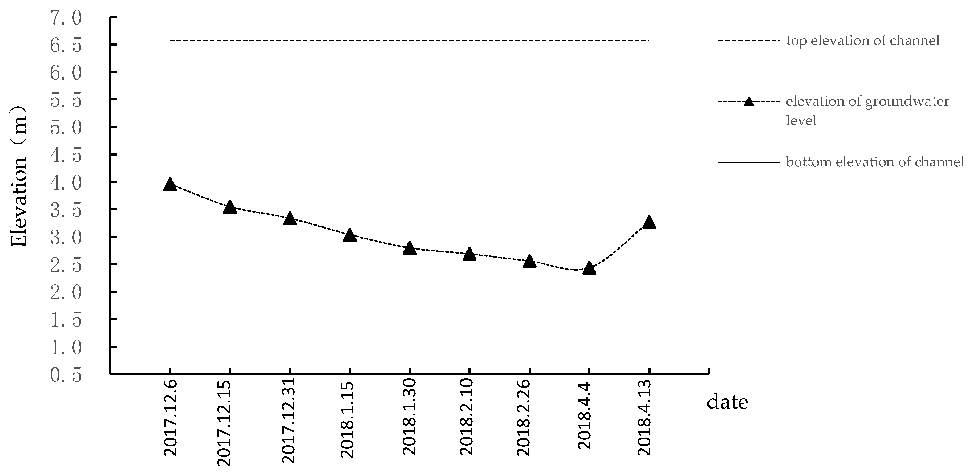
As shown in Figure 4, the groundwater level line was close to the bottom of the channel, so the temperature above the elevation of the groundwater level is below 0 °C because of the minus temperature conduction. Besides, the temperature at the elevation of the groundwater level is greater than or equal to 0 °C. Therefore, the temperature at the elevation of the groundwater level was set at 0 °C. As shown in Figure 4, as time goes by, the elevation of the groundwater level line gradually decreases but it begins to increase after 4 April 2018 This is because the temperature is so low in winter that the water in the base soil will freeze. However, when the temperature rises, the elevation of the groundwater level line will increase because of the melting of the water. The change in the groundwater level line caused the temperature field of the channel to change, and the temperature gradient also changed with time. Therefore, based on the different time-dependent temperature gradients, the equivalent principle was used to define the lower boundary temperature, and different temperatures at the lower boundary were used at different times. The left and right borders extend 2.5 m from the edge of the lining to the sides, and the left and right boundaries were insulated. The vertical displacement of the lower boundary was 0, and the horizontal displacement of the left and right borders was 0.
The change in the groundwater level along the lower boundary with time is illustrated in Figure 4. The change in the lower boundary temperature with time was computed based on the temperature gradient with reference to the change in the groundwater level line. Information about the lower boundary is summarized in Table 1.
If the temperature at the elevation of the groundwater level was set at 0 °C, temperature gradients in the soil change constantly due to the change in the elevation of the groundwater level. However, it is difficult to define a certain value at the lower boundary, so this paper considered the temperature at the lower boundary in 10 February 2018 as 0 °C and then calculates the temperature in the same elevation at a different time. The height difference represents the difference between the groundwater level and top elevation of the channel. The temperature difference represents the difference of the temperature at the groundwater level and the top elevation of the channel. Temperature gradients can be calculated by the height difference and temperature difference. The equivalent height difference represents the difference between the elevation of the groundwater level at 10 February 2018 and other times, so the equivalent temperature at the lower boundary can be obtained by the equivalent height difference and temperature gradients.
3.4. Finite Element Model Calculation and Parameter Selection
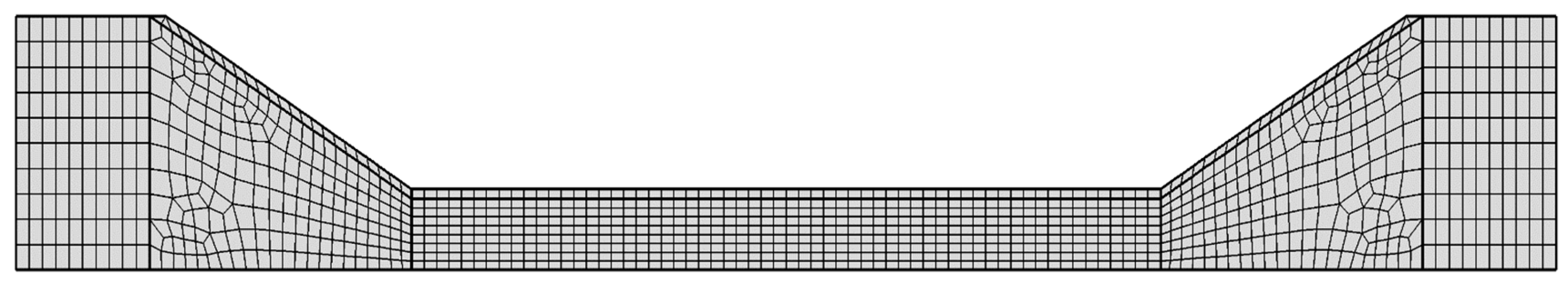
The three physical fields, temperature, water, and stress, were established in the finite element analysis software COMSOL Multiphysics to simulate the physical phenomena in the frozen soil using the differential equations defined above. The “thin layer” in the part of “heat transfer” in COMSOL was used to consider the effect of the compound geomembrane. During the downward freezing process, the frost heave caused volumetric strain in the soil, which caused changes in the soil properties. The parameters, including the thermal conductivity, heat capacity, soil density, and void ratio, varied as the water froze. Figure 5 is the channel finite element mesh.
In this paper, concrete was considered to be an isotropic material. As discussed in the literature [24], the elastic modulus of frozen soil changes with temperature, as shown in Table 2, and the elastic modulus of the unfrozen soil was 15 MPa.
A temperature-dependent melt phase volume fraction, , was introduced to represent the phase change zone between the thawed and frozen soil [20]. The freezing process of the soil was not complete at the freezing point but gradually occurred within a certain temperature range, so the phase transition temperature range was introduced (−1 °C, 0 °C). The phase transition temperature Tf = −0.5 °C, the phase transition interval Tc = 1 °C, and the melt phase volume fraction was defined as follows:
The equivalent principle was used to define the thermal conductivity λ, the equivalent heat capacity Cp, the density ρ, and the void ratio e. The properties of each material are given in Table 3. The frozen soil phase mainly consisted of the soil particle phase, the ice phase, and air. When permafrost thaws, there is no ice left in the soil and this phase is called the melted soil phase. The melted soil phase mainly consisted of the soil particle phase, the water phase, and air. The frozen soil and melted soil phases are indicated by the subscripts f and uf, respectively:
Table 3 shows the values of the compound geomembrane material parameters according to Cai [25]. Table 4 shows the properties of the materials of the channel soil according to previous reports [17,26].
All of these parameters can be input into COMSOL to define some material properties. After that, the distribution of the vertical frost heave, distribution of the temperature, and distribution of the volume fraction of moisture in foundation soil at different times can be obtained respectively.
4. Discussion
Distribution Law of Frost Heave in Basic Soil
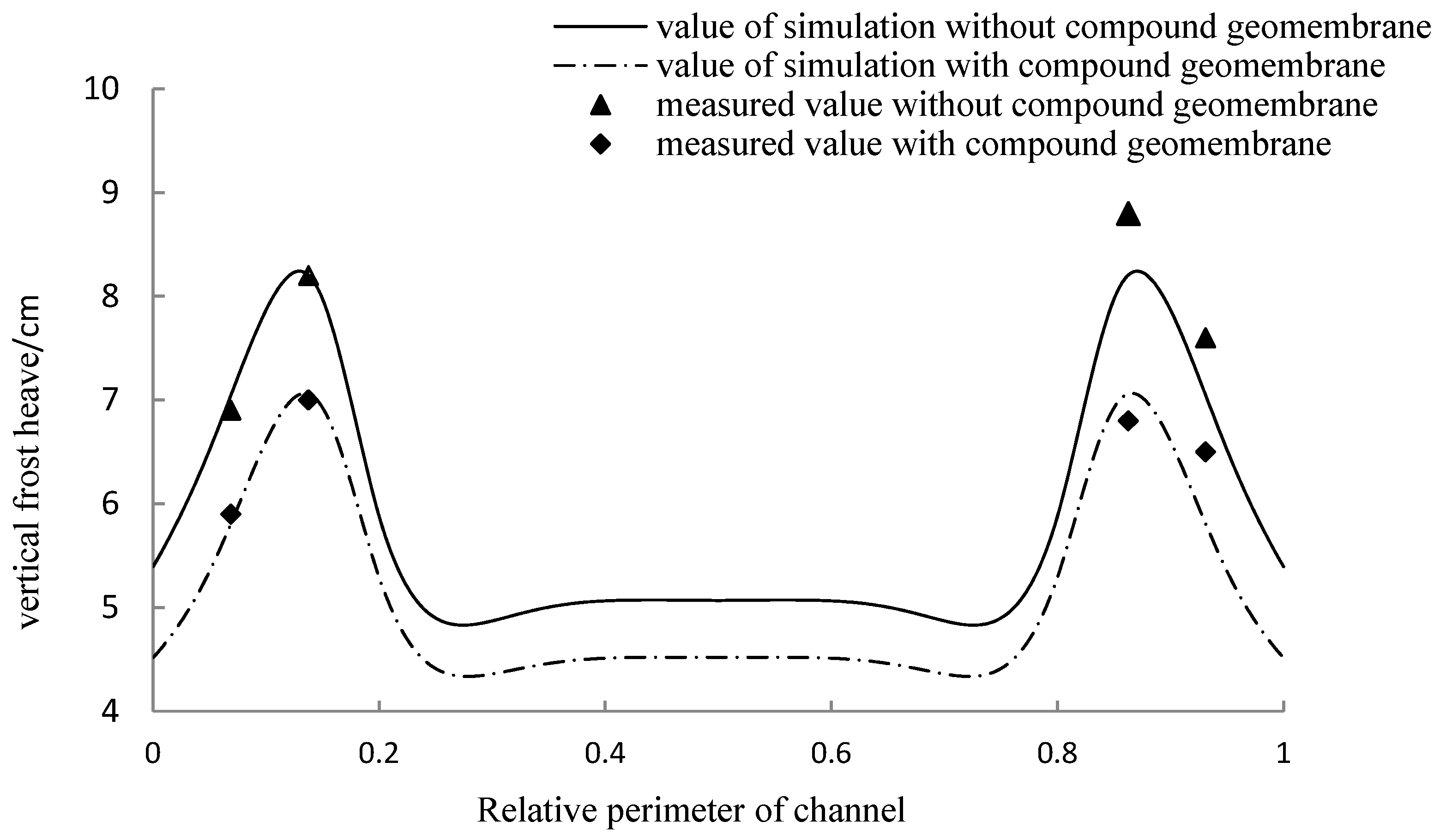
The distribution of the frost heave at each point in the base soil is shown in Figure 6. The measured values were taken at positions one-third and two-thirds of the slope distance from the top of the channel. It can be seen in Table 5 that the deviation between the simulated and measured values was small, indicating that the hydro-thermal coupling model used in the calculation of the normal frost heave amount was reasonable.
As shown in Figure 6, the amount of frost heaving of the base soil reached a maximum at a length of one-third of the slope from the bottom of the channel. The frost heave at the top and bottom of the channel was small. The simulation results are essentially consistent with the measured results. The simulation results in Figure 6 show that when the compound geomembrane was not present, the maximum normal displacements of the lining along the slope and at the top of the channel were 8.243 and 5.394 cm, respectively. When the compound geomembrane was added to the lower side of the lining, the maximum normal displacements along the slope and at the top of the channel were 7.065 and 4.516 cm, respectively. The amount of frost heave decreased by 14.3% and 15.5% after adding the compound geomembrane, which indicates that the presence of the compound geomembrane on the lower side of the lining can reduce the partial frost heave. The compound geomembrane is a type of impervious material composed of geotextile and geomembrane. It has a small thermal conductivity and can create thermal resistance between the lining and foundation soil, which hinders the conduction of heat. Besides, the compound geomembrane changes the contact mechanical behavior between the lining and foundation soil, so the lining and foundation soil will separate and then the air thermal resistance is formed.
The amount of frost heave of the foundation soil was related to many factors, such as the temperature, moisture, and soil quality. The combined effect of the negative temperature and moisture on the soil of the channel caused the soil to heave. Figure 7 shows the temperature distribution in soil in the presence or absence of the compound geomembrane conditions at the right side of channel on 10 February 2018. As shown in Figure 7, when the geomembrane is added on the lower side of the concrete lining, the temperature distribution changes significantly, and the temperature at each point of the base soil is lower. The temperature gradually increases with the decline of the elevation.
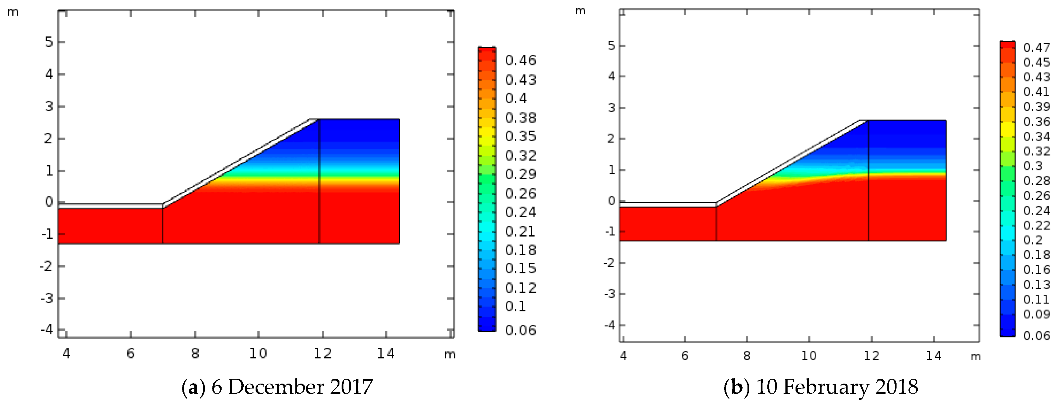
As shown in Figure 8, although the elevation of the groundwater level declined constantly, water migrated upward under the function of the temperature gradients and capillary action. The far side of the concrete lining was most affected. This is because the temperature can be conducted directly through ground without concrete lining.
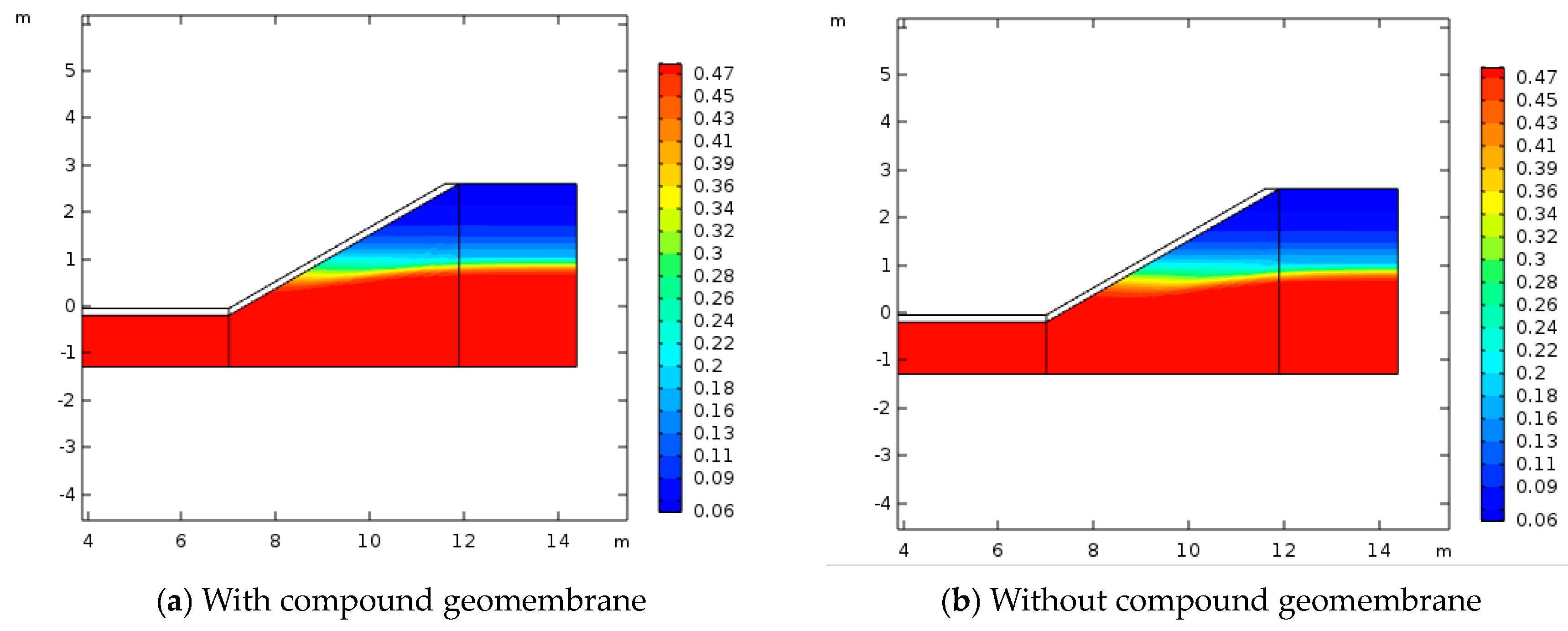
As shown in Figure 9, when the geomembrane is added on the lower side of the concrete lining, the distribution of volume fraction of moisture in soil does not change significantly. The base soil is filled with water below the height of one-third of the slope from the bottom of the channel. However, the volume fraction of moisture in soil decreases gradually with the height increasing.
At the top of the channel, although the temperature was lower, the moisture content was small, and the replenishment was insufficient. Thus, the frost heaving amount was small. At the bottom of the channel, although the moisture content was large and the recharge was sufficient, the negative temperature conduction was slow, and the temperature was high. Thus, the frost heaving amount was small too. On the other hand, at about one-third of the slope from the bottom of the channel, heat was transferred to the base soil through the lining and to the ground through the base soil on both sides of the lining, resulting in a low temperature. Besides, in this position, the water content was replenished, and the supply was sufficient. Due to the combined effect of the low temperature and sufficient amount of water, the amount of frost heaving was large. In this simulation example, the groundwater level was shallow. Under the combined action of capillary action and a temperature gradient, the water continuously migrates to the frozen front, but the phase change of the moisture during the freezing process generates heat, which hinders the process to some extent.
5. Conclusions
- (1)
- A hydrothermal three-field coupling simulation was carried out on the trapezoidal channel with a compound geomembrane on the lower side of the lining. The simulation also considered the influence of groundwater-level changes on the temperature field and the effect of capillary action on water migration. The simulation results were basically consistent with the measurements, revealing the frost heave distribution of the trapezoidal channel. According to the simulation results, the amount of frost heaving of the base soil reached a maximum at a length of one-third of the slope from the bottom of the channel at 8.243 cm. In the bottom and top of the channel, the frost heave was small.
- (2)
- The addition of the compound geomembrane had little effect on the moisture transfer, but it could change the distribution of the temperature in the base soil to a large extent. Therefore, the main reason why the frost heaving of the channel reduced was that it can form thermal resistance between the concrete lining and base soil. The frost heave decreased by 14.3% and 15.5% at a distance of one-third from the bottom of the channel along the slope and at the top of the channel, respectively.
Author Contributions
Conceptualization, T.M. and Z.L.; methodology, T.M.; software, T.M.; validation, T.M., Z.L.; formal analysis, T.M.; investigation, T.M.; resources, Z.L.; data curation, T.M.; writing—original draft preparation, T.M.; writing—review and editing, T.M.; visualization, T.M.; supervision, Z.L.; project administration, Z.L.; funding acquisition, Z.L. All authors have read and agreed to the published version of the manuscript.
Funding
This research was supported by the National Key Research and Development Program for the 13th Five-year Plan [grant number 2016YFC0400203] and the 12th Five-year National Science and Technology Support Program [grant number 2012BAD08B01].
Acknowledgments
In this section you can acknowledge any support given which is not covered by the author contribution or funding sections. This may include administrative and technical support, or donations in kind (e.g., materials used for experiments).
Conflicts of Interest
The authors declare no conflict of interest.
References
- Xu, X.Z.; Wang, J.C.; Zhang, L.X. Frozen Soil Physics; Science Press: Beijing, China, 2001. [Google Scholar]
- Ma, W.; Wang, D.Y. Frozen Soil Mechanics; Science Press: Beijing, China, 2014. [Google Scholar]
- Song, Q.L.; He, W.Q.; Li, G.; Zhao, H.W.; Zhang, Y.F. The research on insulation and frost heave control for concrete lining canal. J. Irrig. Drain. 2015, 34, 43–48. [Google Scholar]
- Hao, J.C.; Lou, Z.K.; Gao, F. Numerical simulation and slope coefficient optimization of frost heave of trapezoidal channel. J. Irrig. Drain. 2017, 36, 81–86. [Google Scholar]
- Mu, S.; Ladanyi, B. Modeling of coupled heat, moisture and stress field in freezing soil. Cold Reg. Sci. Tech. 1987, 14, 237–246. [Google Scholar] [CrossRef]
- Masters, I.; Pao, W.K.S.; Lewis, R.W. Coupling temperature to a double-porosity model of deformable porous media. Int. J. Numer. Methods Eng. 2000, 49, 421–438. [Google Scholar] [CrossRef]
- Li, S.Y.; Zhang, M.Y.; Pei, W.S.; Lai, Y.M. Experimental and numerical simulations on heat-water-mechanics interaction mechanism in a freezing soil. Appl. Therm. Eng. 2018, 132, 209–220. [Google Scholar] [CrossRef]
- Bai, R.Q.; Lai, Y.M.; Zhang, M.Y.; Gao, J.Q. Water-vapor-heat behavior in a freezing unsaturated coarse-grained soil with a closed top. Cold Reg. Sci. Tech. 2018, 155, 120–126. [Google Scholar] [CrossRef]
- He, Z.Y.; Zhang, S.; Teng, J.D.; Yao, Y.P.; Sheng, D.C. A coupled model for liquid water-vapor-heat migration in freezing soils. Cold Reg. Sci. Tech. 2018, 148, 22–28. [Google Scholar] [CrossRef]
- Zhu, Z.W.; Ning, J.G.; Ma, W. Constitutive model and numerical analysis for the coupled problem of water, temperature and stress fields in the process of soil freeze-thaw. Eng. Mech. 2007, 24, 138–144. [Google Scholar]
- Mao, X.S.; Li, N.; Wang, B.G.; Hu, C.S. Analysis model of stress and deformation of permafrost Subgrade with phase changing. J. Traffic Transp. Eng. 2007, 7, 58–62. [Google Scholar]
- Huo, X.L.; Chen, S.G.; Wei, M.M.; Xiao, X. Study on frozen-thaw stability of subgrade in seasonal frozen soil with phase changing. Cons. Tech. 2013, 42, 93–96. [Google Scholar]
- Wang, T.H.; Hu, C.S.; Ning, L. Simulation method for calculating stress and deformation of highway embankment on frozen soil area. Cold Reg. Sci. Tech. 2005, 42, 89–95. [Google Scholar] [CrossRef]
- Li, Z.; Liu, S.H.; Feng, Y.T.; Liu, K.; Zhang, C.C. Numerical study on the effect of frost heave prevention with different canal lining structures in seasonally frozen ground regions. Cold Reg. Sci. Tech. 2013, 85, 242–249. [Google Scholar] [CrossRef]
- Li, S.Y.; Zhang, M.Y.; Tian, Y.B.; Pei, W.S.; Zhong, H. Experimental and numerical investigations on frost damage mechanism of a canal in cold regions. Cold Reg. Sci. Tech. 2015, 116, 1–11. [Google Scholar] [CrossRef]
- Liu, Y.; Wang, Z.Z.; Wang, Y.; Liu, Q.H.; Guo, R.; Xiao, M. Frost heave model of canal considering influence of moisture migration and phase transformation on temperature field. Trans. Chin. Soc. Agric. Eng. 2016, 32, 83–88. [Google Scholar]
- Wang, Z.Z.; Liu, S.J.; Wang, Y.; Liu, Q.H.; Ge, J.R. Size effect on frost heave damage for lining trapezoidal canal with arc-bottom in cold regions. J. Hydraul. Eng. 2018, 49, 803–813. [Google Scholar]
- Zienkiewicz, O.C.; Taylor, R.L.; Fox, D. The Finite Element Method for Solid and Structural Mechanics, 7th ed.; Elsevier: Singapore, 2013. [Google Scholar]
- Jame, Y.W.; Norum, D.I. Heat and mass transfer in a freezing unsaturated porous medium. Water Resour. Res. 1980, 16, 811–819. [Google Scholar] [CrossRef]
- Zhou, J.Z.; Li, D.Q. Numerical analysis of coupled water, heat and stress in saturated freezing soil. Cold Reg. Sci. Tech. 2012, 72, 43–49. [Google Scholar] [CrossRef]
- Konrad, J.M.; Morgenstern, N.R. Prediction of frost heave in the laboratory during transient freezing. Can. Geotech. J. 1982, 19, 250–259. [Google Scholar] [CrossRef]
- Kay, B.D.; Groenevelt, P.H. On the interaction of water and heat transport in frozen and unfrozen soils: Basic theory; the vapor phase. Soil Sci. Soc. Am. J. 1974, 38, 395–400. [Google Scholar] [CrossRef]
- Peck, R.B.; Hansen, W.E.; Thornburn, T.H. Foundation Engineering, 2nd ed.; Wiley: New York, NY, USA, 1974. [Google Scholar]
- Wang, Z.Z.; Shao, J.D.; Jiang, Y.J.; Zhang, C.Q. Nonlinear finite element analysis of interaction of orthotropic frozen ground and construction. China Civ. Eng. J. 1999, 32, 55–60. [Google Scholar]
- Cai, Z.W. Study on Thermal Conductivity of Filled Polypropylene. Master’s Thesis, Zhongshan University, Guangzhou, China, June 2005. [Google Scholar]
- Liu, W.M.; He, P.; Zhang, Z. A calculation method of thermal conductivity of soils. J. Glaciol. Geocryol. 2002, 24, 770–773. [Google Scholar]
Figure 1.
Prototype channel (unit: m).

Figure 2.
The layout of observation points.

Figure 3.
The ambient temperature changes with time.

Figure 4.
Groundwater level line changes with time.

Figure 5.
Finite element mesh.

Figure 6.
Distribution of the vertical frost heave at each point of the lining.

Figure 7.
Distribution of the temperature in the foundation soil.

Figure 8.
Distribution of volume fraction of moisture in foundation soil at different times.

Figure 9.
Distribution of the volume fraction of moisture in foundation soil.


Table 1.
Lower boundary equivalent temperature calculation table.
| Date | Height Difference (m) | Ground Temperature (°C) | Temperature Gradient (°C m−1) | Equivalent Height Difference (m) | Equivalent Temperature (°C) |
|---|---|---|---|---|---|
| 6 December 2017 | 2.62 | −5.5 | 2.10 | 1.27 | 2.67 |
| 15 December 2018 | 3.03 | −8.0 | 2.64 | 0.86 | 2.27 |
| 31 December 2018 | 3.24 | −10.0 | 3.09 | 0.65 | 2.01 |
| 15 January 2018 | 3.54 | −10.0 | 2.82 | 0.35 | 0.99 |
| 30 January 2018 | 3.78 | −7.5 | 1.98 | 0.11 | 0.22 |
| 10 February 2018 | 3.89 | −9.5 | 2.44 | 0 | 0.00 |
Table 2.
Modulus of the foundation soil.
| Properties | Value | |||
|---|---|---|---|---|
| Temperature/°C | −1 | −2 | −3 | −5 |
| Elastic modulus/MPa | 19 | 26 | 33 | 46 |
Table 3.
Value of the composite geomembrane material parameters.
| Material | Thickness (mm) | Number of Layers | Thermal Conductivity (W/(m·K)) | Specific Heat Capacity (kJ/(kg·K)) | Density (kg/m3) |
|---|---|---|---|---|---|
| Geotextile | 3 | 2 | 0.241 | 1.88 | 133 |
| PE film | 0.3 | 1 | 0.16 | 0.9 | 1400 |
| air | 8 | 1 | 0.02 | 1.003 | 1.29 |
Table 4.
Material parameters.
| Material | Thermal Conductivity (W/(m·K)) | Specific Heat Capacity (kJ/(kg·K)) | Density (kg/m3) |
|---|---|---|---|
| Concrete | 1.58 | 0.97 | 2250 |
| Ice | 2.2 | 2.1 | 917 |
| Soil | 1.5 | 0.92 | 1390 |
| Water | 0.6 | 4.2 | 1000 |
| Air | 0.02 | 1.003 | 1.29 |
Table 5.
Measured values and analog value error.
| Lining Form | One-Third of the West Slope | Two-Thirds of the West Slope | One-Third of the East Slope | Two-Thirds of the East Slope |
|---|---|---|---|---|
| With geomembrane | 1.45% | 0.07% | 6.93% | 6.72% |
| Without geomembrane | 1.69% | 0.86% | 3.82% | 3.33% |
© 2020 by the authors. Licensee MDPI, Basel, Switzerland. This article is an open access article distributed under the terms and conditions of the Creative Commons Attribution (CC BY) license (http://creativecommons.org/licenses/by/4.0/).
Share and Cite
MDPI and ACS Style
Mo, T.; Lou, Z. Numerical Simulation of Frost Heave of Concrete Lining Trapezoidal Channel Under an Open System. Water 2020, 12, 335. https://doi.org/10.3390/w12020335
AMA Style
Mo T, Lou Z. Numerical Simulation of Frost Heave of Concrete Lining Trapezoidal Channel Under an Open System. Water. 2020; 12(2):335. https://doi.org/10.3390/w12020335
Chicago/Turabian StyleMo, Tengfei, and Zongke Lou. 2020. "Numerical Simulation of Frost Heave of Concrete Lining Trapezoidal Channel Under an Open System" Water 12, no. 2: 335. https://doi.org/10.3390/w12020335
Note that from the first issue of 2016, this journal uses article numbers instead of page numbers. See further details here.