Discharge Coefficient of a Round-Crested Weir

State Key Laboratory of Hydraulics and Mountain River Engineering, Sichuan University, Chengdu 610065, China
*
Author to whom correspondence should be addressed.
Water 2019, 11(6), 1206; https://doi.org/10.3390/w11061206
Submission received: 17 May 2019
/
Revised: 3 June 2019
/
Accepted: 4 June 2019
/
Published: 10 June 2019
(This article belongs to the Section Hydraulics and Hydrodynamics)
Abstract
:A model experimental study was conducted for the discharge capability of different shapes of the crest of a weir. The flow rate and the head over the weir measured by laboratory experiments were used as two parameters for characterizing the head discharge relationship. Experiments indicated that the head discharge relationship for different radii located upstream and downstream of the crest of the weir had different features. A series of detailed experiments investigated the effects of different upstream rounding radii on the discharge capability when the downstream rounding radius was constant and the round ratio between the radius of the rounded upstream corner to the weir breath in the direction of flow was equal to 1.00. Experimental results showed that the rounded upstream corner could increase the discharge capability. The discharge capability increased as the upstream round ratio became larger and did not change when the round ratio varied from 0.10 to 0.30 and from 0.75 to 1.00 in this experiment. Based on the experimental data distribution, the empirical formula for the discharge coefficient was fitted with the round ratio as the group parameter.
1. Introduction
Weirs of different shapes are extensively used as measuring devices and control structures in laboratories, irrigation projects, and hydraulic engineering. Determining the discharge coefficient in open channels is one of the primary issues in hydraulic engineering. According to the weir width, weirs can generally be classified into two categories: finite crest length weirs and sharp-crested weirs (or thin-plate weirs).
A rectangular thin-plate weir is characterized by having no effect on a free-falling nappe and a good relationship between the head over the weir and flow. The upstream water level is headed up by the control structure, and the flow is formed under the action of gravity. The centrifugal inertial force has a certain influence on the pressure distribution on the surface of the building and the discharge capacity of the building. When a sharp-crested weir is used in irrigation projects and hydraulic engineering, there are sediments and sundries in the water, which will damage the crest. Therefore, the flow rate cannot be accurately measured. A weir with a rounded upstream corner can increase the discharge capacity and improve the above situation, especially when the weir height is small.
Azimi and Rajaratnam [1] studied weirs of a finite crest length and classified them into four groups: long-crested weirs, broad-crested weirs, short-crested weirs, and sharp-crested weirs, defined by the range of h/L > 2, where h is the upstream, and L is the crest length. For a rectangular thin-plate weir, the classical discharge equation derived from energy consideration [2] can be written as follows:
where Q is the discharge, w is the width of the open channel, h is the upstream measured head, g is the acceleration of gravity, and Cd is the discharge coefficient in connection with the upstream head, assuming that the velocity head and surface tension are not taken into consideration.
Many researchers have conducted extensive experiments on the determination of the discharge coefficient and derived different calculation formulas. When processing hydraulic problems involving heuristic engineering reasoning in the face of model testing and actual prototype implementation, James [3] proposed that it is best handled by physical models. For the round-crested weir used in this experiment, based on dimensional analysis, the equation for the discharge coefficient and other parameters can be written as follows:
where h is the upstream measured head, P is the height of the thin-plate weir, b is the half weir width in the direction of the channel, and r is the radius of the upstream corner of the weir.
For the broad-crested weir with round upstream edges, Harrison [4] proposed an expression based on an application of critical flow theory and took account of the boundary-layer development in order to calculate the discharge coefficient. Smith [5] studied the discharge characteristics and the effects of rounded upstream corners by conducting an investigation with two models, and Tracy [6] provided a comprehensive summary of previous studies on flow regime over rectangular broad-crested weirs with upstream corners of three shapes.
For the square-edged broad-crested weir, Hall [7] proposed an equation for the free flow characteristics based on boundary-layer theory, and utilized the experimental data of Bazin [8] to verify this equation. Applying the momentum relationship, Doeringsfeld and Baker [9] derived a theoretical formula for the flow rate over a squared-edged, rectangular, and broad-crested weir. Surya Rao [10] analyzed the characteristics of flow over broad-crested weirs with square and elliptical upstream corners in order to study the effect of finite crest length. For the rounded-crested weir, Ruschak and Weinstein [11] analyzed the viscous flow of the gravity-driven flow over a round-crested weir, and proposed an empirical equation between the head and the velocity. Honar [12] found that under subcritical flow conditions, the side enthalpy exit occurred 10% more frequently with a rounded edge inlet than a squared edge entrance.
Ramamurthy et al. [13] found that the discharge coefficient of round-nosed broad-crested weirs can be calculated based on the upstream head, due to its relationship with the radius of the upstream crested corner, and that the flow characteristic depends on the ratios of H/L and R/P, where H is upstream head, R is the radius of the upstream top corner, L is length of weir, and P is height of weir. When R/P is between 0.000 and 0.094, the presence of a rounded upstream corner has no effect on the natural outflow over the weir. As R/P increases from 0.094 to 0.250, the discharge coefficient increases gradually. Formulation of the discharge coefficient for free flow based on momentum relationships was proposed.
Abou-seide and Quraishi [14] conducted eight sets of experiments with upstream edge rounding, and found that the maximum value of the discharge coefficient was obtained when the ratio between the radius of the rounded upstream corner to the weir breadth in the direction of flow was greater than or equal to 0.75. Harrison [4] and Woodburn [15] suggested that the discharge coefficient of a broad-crested weir increased by reducing flow separation as R/Hmax was increased up to 0.11, where R is the rounded upstream corner and Hmax is the maximum value of the upstream total head, and stated that the discharge coefficient did not increase distinctly when R/Hmax was increased beyond 0.11.
Previous studies on weirs with rounded upstream corners were mostly based on broad-crested weirs. Hager [16] considered the measurement accuracy of the broad-crested weir to be relatively low and stated that the hydraulic characteristics are too poor as an overflow structure. In this article, a series of comprehensive experiments are investigated to study the hydraulic characteristics of flow over a round-crested weir with a thickness of 0.02 m. An experiential formula for the discharge coefficient based on the experimental data collected is developed.
2. Experimental Setup
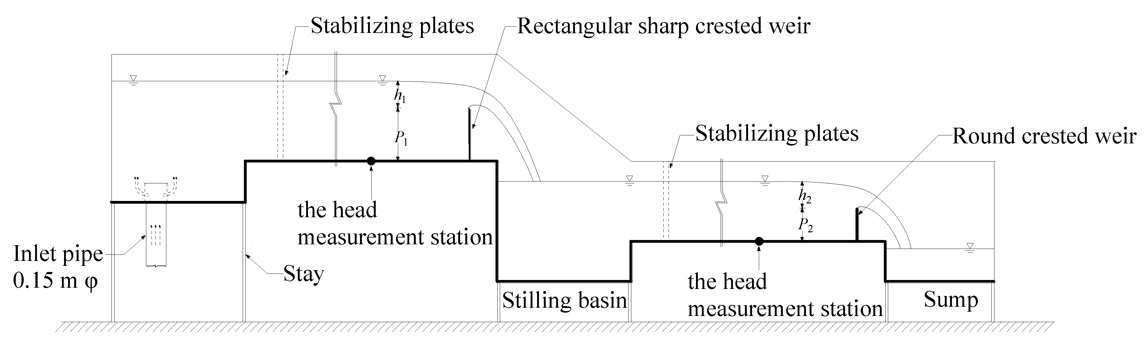
The experimental procedure consisted of measuring the flow rate of the open-horizontal channel and determining the discharge coefficient of the round-crested weir, shown in Figure 1. According to the water flow path, the first rectangular channel, which was 7.00 m long, 0.52 m wide, and 0.80 m deep, and the next one, which was 7.00 m long, 0.52 m wide, and 0.70 m deep, were used for the tests.
After the flow came out of the inlet pipe, there was a holding sheet above the entrance to decrease the flow velocity and thus stop surface waves caused by fluctuation in the entrance. The floor and side walls of the channel were made of transparent 0.01 m thick tempered glass. The stilling basin, which was 1.00 m long, was 0.30 m lower than the downstream floor to eliminate the kinetic energy of the flow passing through the rectangular sharp-crested weir.
James [17] proposed that model construction quality and flow measurement method can cause differences in discharge capability of models and prototypes. The flow rate of a rectangular sharp-crested weir (scw) can be measured with an electronic flow-meter with a precision of ±0.5%. The weir was made of 0.01 m thick and 0.40 m high plexiglass, with a 60° downstream incline at the crest. Bos [2] proposed a discharge coefficient calculation formula of a sharp-crested weir in a full-width channel, as shown in Equation (3). The flow calculated by Equations (1) and (3) was compared with the electronic flow meter reading.
Aydin et al. [18] pointed out that the head discharge relationship is related to the weir’s height for a larger flow rate if P ≤ 0.04 m. Based on Kindsvater and Carter’s [19] data, the minimum height of the sharp-crested weir was suggested to be 0.10 m by Bos [2]. The round-crested weirs, as shown in Figure 2 and Table 1, were made of 0.02 m thickness and 0.25 m high plexiglass in order to ensure that the discharge and the weir’s height were independent of measured heads.
In order to determine the head discharge relationship of a round-crested weir with round upstream corners of different radii, accurate measurement of the head was required, and each geometry was investigated twice. A vent should be provided downstream of the weir in order to prevent negative pressure and form a free-falling nappe. A camera (Nikon D5300 AF-P 18-55, Nikon Optical Instruments (China) Co., Ltd, Wuxi City, China) was used to take pictures of the form of the nappe during the experiment. Measurements were made by the SDA1000 sensor data acquisition system (Chengdu Yufan Technology Co., Ltd, Chengdu City, China) and the point gages (Beijing Zhecheng Technology Co., Ltd, Beijing City, China), and the average value was taken as the water head. The accuracy of the point gages was 0.1 mm, and the accuracy of SDA1000 sensor data acquisition system was 0.01 mm. Bos [2] suggested that the head measurement station should be fixed at an appropriate upstream distance equal to between three and four times the maximum head over the weir in order to avoid the area of the surface being drawn down. The point for measuring the water head was set at a distance of 1.00 m from the round-crested weir.
3. Analysis of Data
3.1. Discharge Characteristic
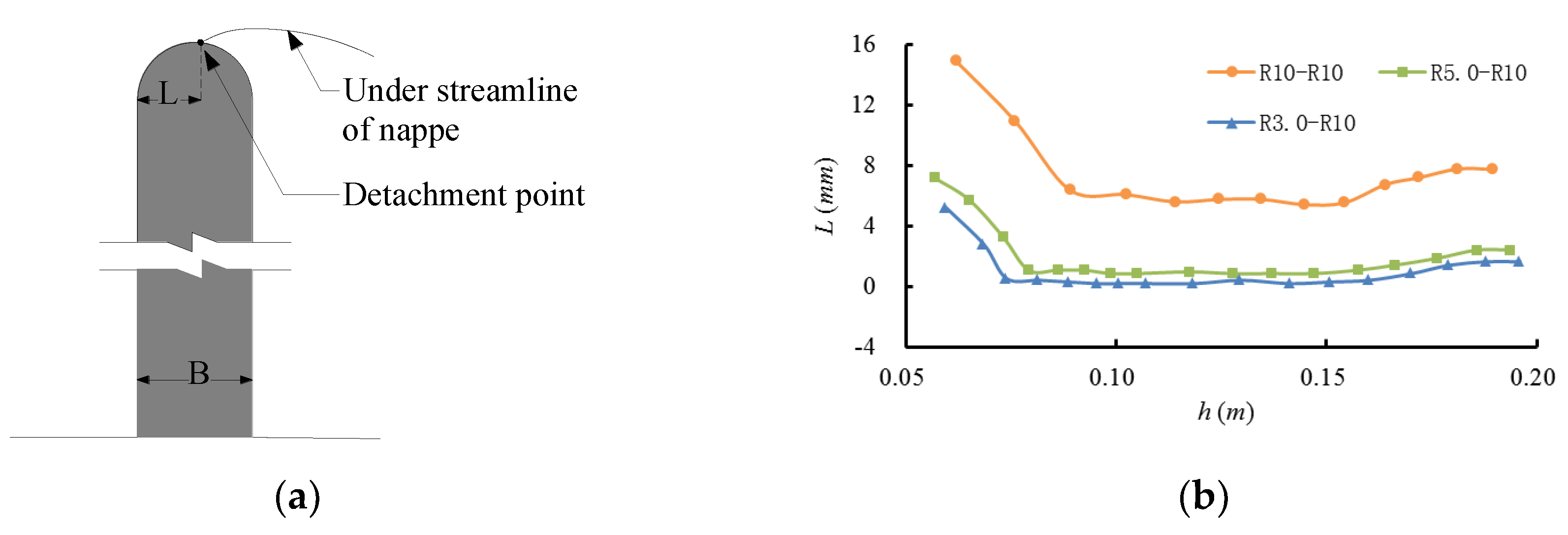
When using the sharp-crested weir as a classical flow measuring device, the contact between crest and nappe is only one line at the crest of the weir, and the place where the nappe leaves the weir always maintains the line and does not change as the flow increases. Based on previous investigations, Horton [20] obtained the relationship between the veritable head and the measured head by improving the equation derived by Stearns and Fteley [21], because the presence of the upstream rounded upstream corner will reduce the vertical contraction and flow separation of water passing over the weir, ultimately virtually lowering the weir. As shown in Figure 3, the detachment point of a round-crested weir gradually moves upstream on the top of the weir as the measured head increases. Through observation of the experimental photos, when the discharge rate is increased to 0.021 m3/s (R3.0-R10), 0.023 m3/s (R5.0-R10), and 0.029 m3/s (R10-R10), the detachment point does not change. The detachment point will move downstream when the discharge rate is greater than 0.065 m3/s. For the convenience of calculation, the height of the weir plate is equal to 0.25 m, not the position of the detachment point.
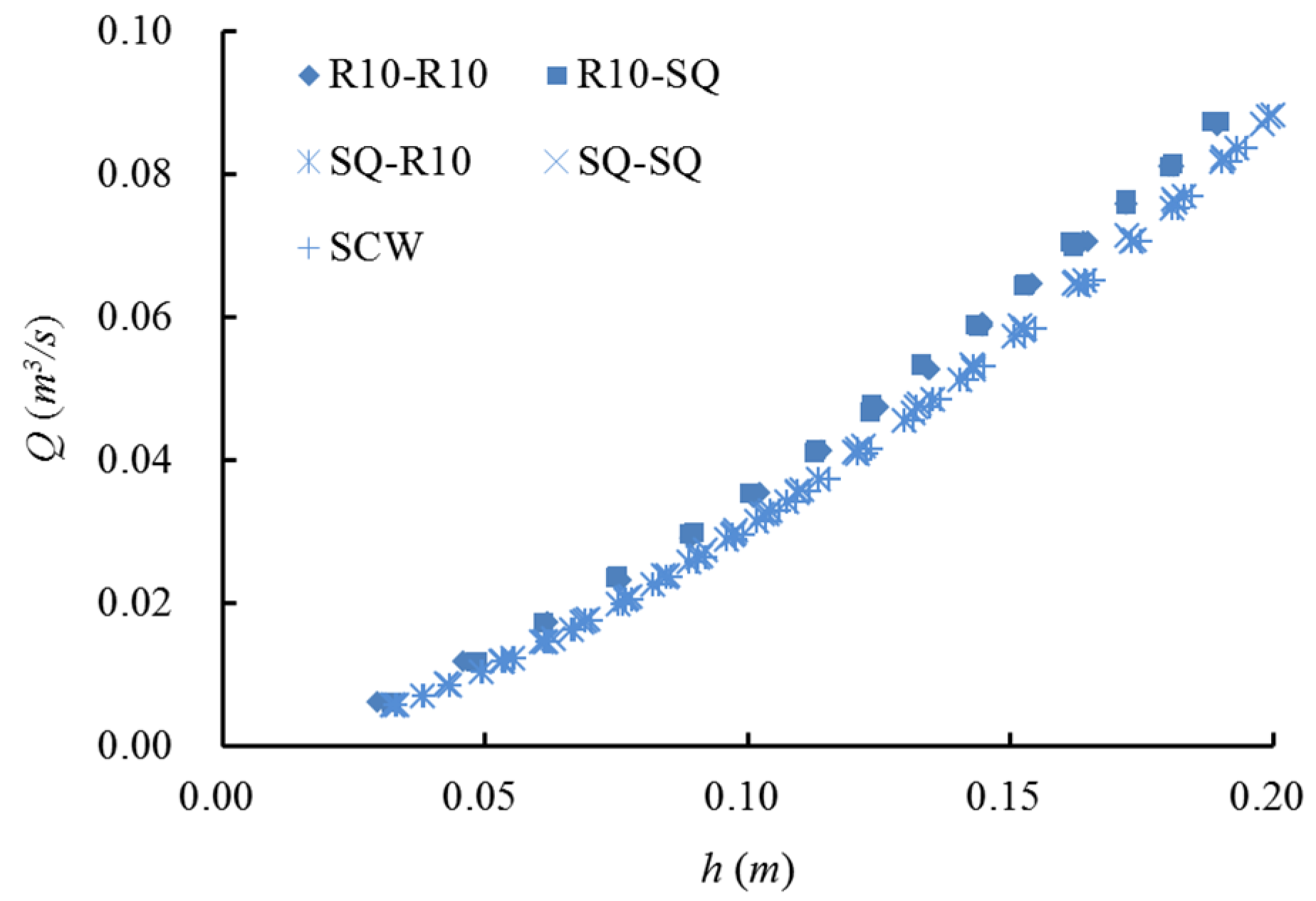
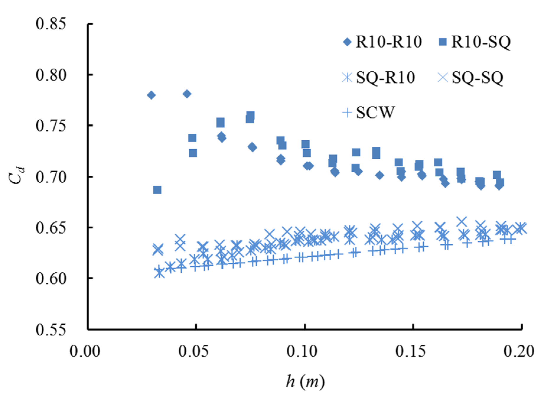
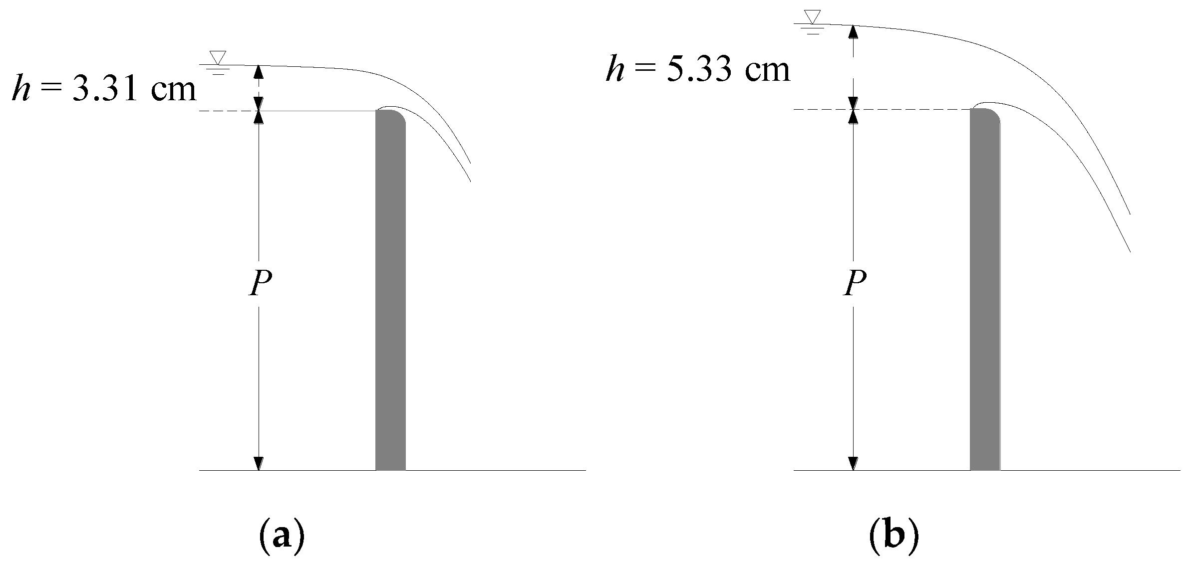
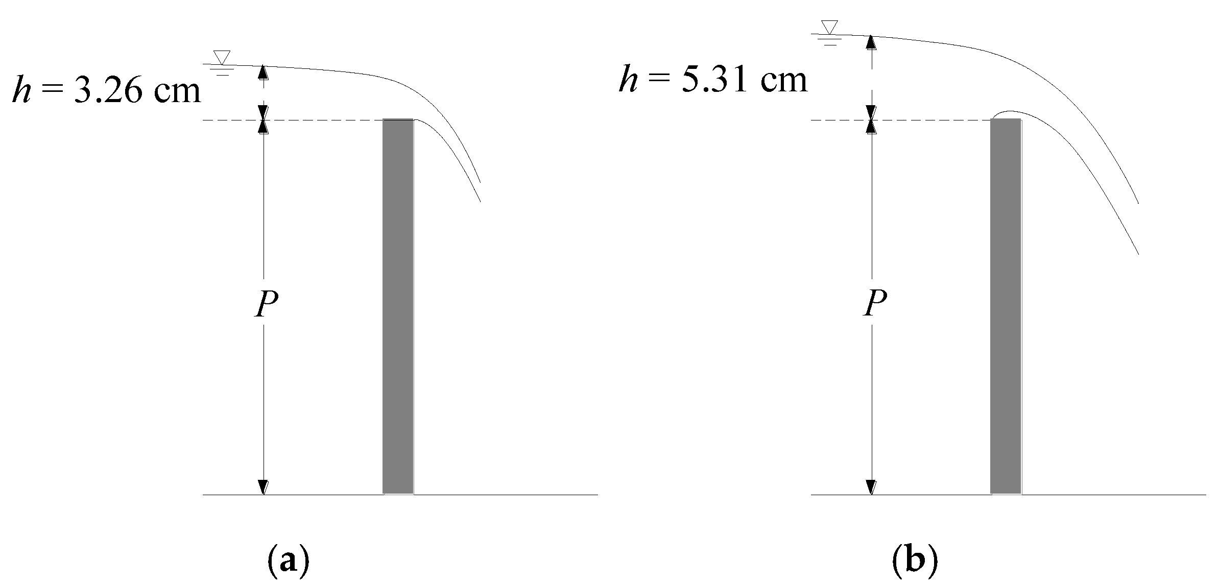
When making a sharp-crested weir used in irrigation, laboratories, and industry, it should have a 60° downstream incline at the crest in order to ensure that the contact of the crest of the weir and the nappe is in one place and the downstream corner of the weir has no effect on the nappe. As shown in Figure 4, the relationship of the head discharge of experimental weirs of different crest-shapes was good. When the head was small, the width of the weir plate had a great influence on the flow characteristic and discharge capability. As shown in Figure 5, for Q < 0.017 m3/s, two nappes of R10-R10 and R10-SQ were separated from the crest at the downstream corner, and the discharge capability of the second one was relatively small because the squared downstream corner of the weir raised the water level. The weir, namely SQ-SQ, was equivalent to a short-crested weir for a small head, Q < 0.012 m3/s, and the nappe left the downstream corner and did not jump, as shown in Figure 6 and Figure 7, so the flow coefficient of SQ-SQ was larger than SQ-R10. When the discharge rate over the weir reached a certain value, 0.015 m3/s, the downstream angle of the crest did not affect the nappe, and the weir of the same upstream corner had the same discharge capability.
As shown in Figure 6b and Figure 7b, the shape of the crest with a squared upstream corner and smaller thickness did not affect the discharge capability. Its discharge characteristics were similar to those of a sharp-crested weir, and the nappe was separated from the crest at the upstream corner. When the flow rate reached a certain level, greater than 0.015 m3/s, the weir plate, namely SQ-R10 or SQ-SQ, had the same flow capacity as the sharp-crested weir, meaning the flow rate could also be measured by this weir plate instead of a sharp-crested weir in a laboratory or irrigation setting.
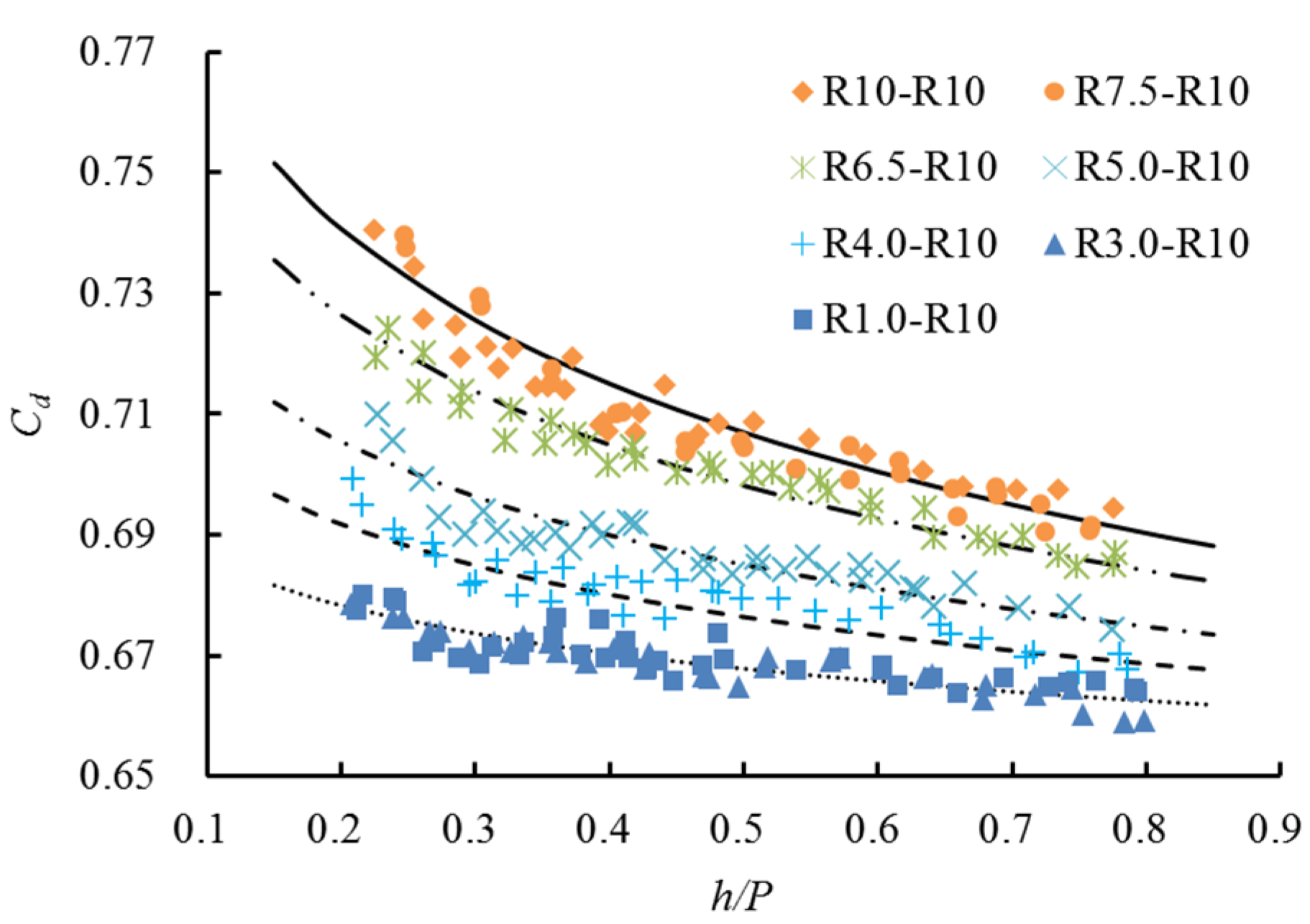
Abou-seida [14] proposed that the flow coefficient will remain the same when r/B ≥ 0.75, where r is the radius of the curve and B is the weir breadth in the direction of flow. As seen in Figure 8, the presence of the round upstream corner increased the discharge capability of the weir plate. The discharge coefficient of round-crested weirs with different radii became larger as r/b increased up from 0.30 to 0.75. When r/b changed from 0.10 to 0.30 and from 0.75 to 1.00, the discharge coefficient remained the same.
3.2. Formulation for Discharge Coefficient
Five models with upstream corners of different radii were studied in this experiment, and r/b changed from 0.10 to 1.00. It can be seen from the above analysis that when r/b was 0.00, the upstream corner was a rectangular corner and the flow characteristics were quite different from the rest of the model, so they were not considered when deriving the formulation for the discharge coefficient. Bos [2] proposed that the head of a sharp-crested weir should be greater than 0.03 m to ensure that the nappe is completely free from the weir crest after passing the weir. Considering the instability of the flow and the effect of the downstream corner on the nappe when the head was small, the minimum head for deriving the equation was 0.05 m.
As shown in Figure 8, the change rule of the discharge coefficient with head to height was obvious, and the rules for different radii were similar. As a prominent method exploited in previous research, the formulation for the discharge coefficient was derived from experimental data, which should be a function of the dimensionless parameters listed in Equation (2). According to the good experimental data distribution and Equation (2), the best fit function of the discharge coefficient was assumed to be of the following form:
where k1 and k2 are parameters that are calculated by r/b. It can be seen from Figure 8 that when r/b increases from 0.30 to 0.75, k1 increases and k2 decreases. b is the half width of the round weir, and the half width of the weir near the downstream was not in contact with the flow and did not affect the nappe. The equations for k1 and k2 can be written as follows:
Based on a multivariate optimization approach, the best fit parameters were derived by using all of the five data sets of the present experiment in the range of a round-crested weir, and two calculated expressions were obtained:
Incorporating Equations (6) and (7) into Equation (3), the formula for the discharge coefficient can be written as
where h = 0.05–0.20 m, and r/b = 0.30–0.75.
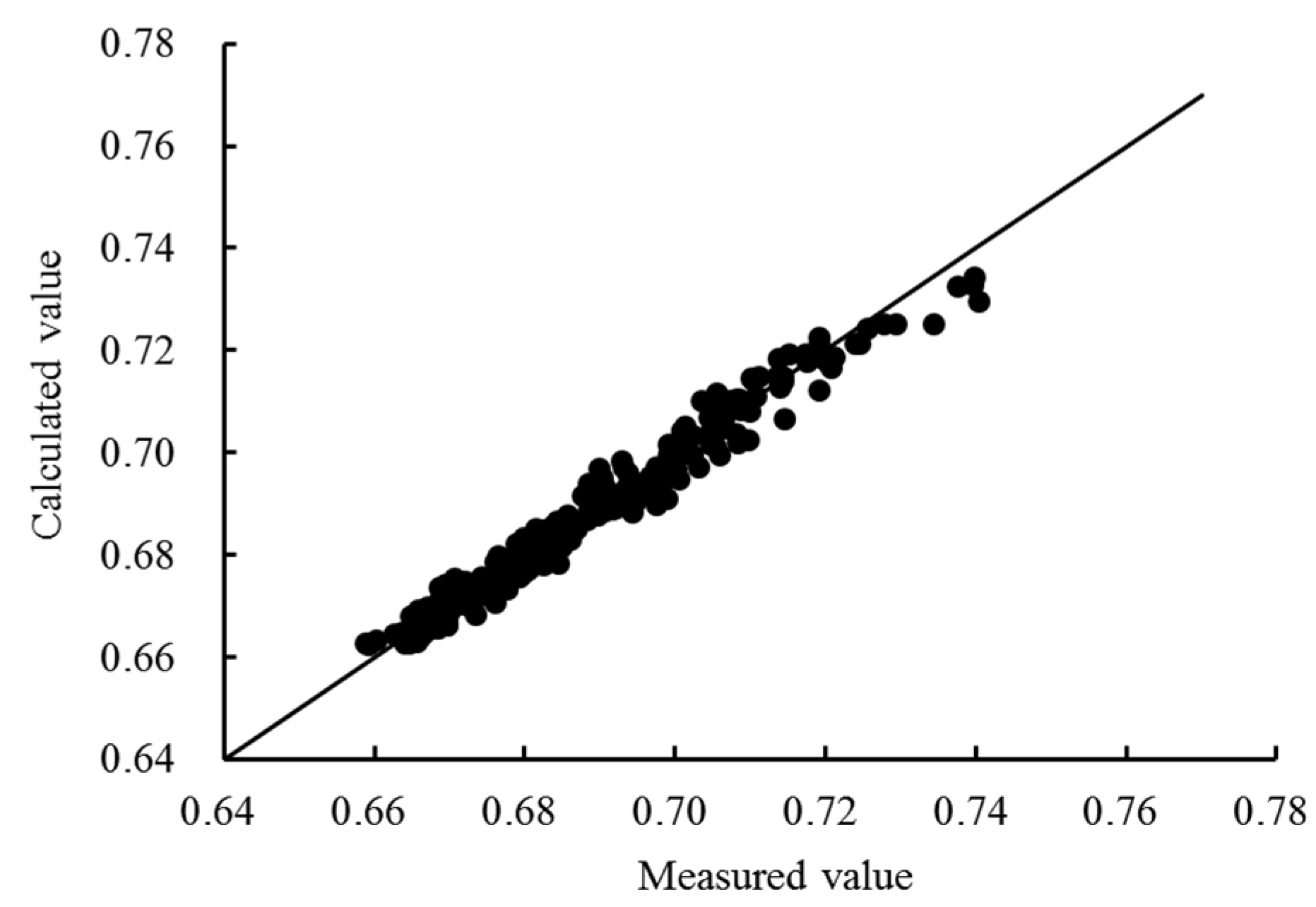
As shown in Figure 9, the measured Cd and the calculated Cd matched well. All data points were within ±2% of the total error. The error of the calculated value was within an acceptable range. It is clear from the above discussions that Equation (8) derived by empirical fit can be used for calculating the discharge coefficient for a round-crested weir.
4. Conclusions
This article discussed a round-crested weir based on experimental data, with the purpose of establishing flow characteristics and influencing the rules regarding changes in body shape, and proposed a best fit expression for the discharge coefficient. Results showed that the shape of the downstream corner caused the flow pattern of the small flow to be different. When the downstream corner did not affect the nappe, the flow patterns of the two were consistent. It was observed that a weir with a rectangular upstream corner and small width, which did not affect the nappe, could be used as a sharp-crested weir. Experimental data showed that the rounded upstream corner was able to increase the discharge capability, with the discharge capability increasing with increases in the round ratio. When the round ratio varied from 0.10 to 0.30 and from 0.75 to 1.00, the value and the variation law of the flow coefficient were consistent.
Author Contributions
This paper is a product of joint efforts of the authors who worked together on the experimental model tests. J.D. has a scientific background in discharge measurement structures, while J.G. and W.W. conducted the experimental investigations. J.D. and W.W. generated the influence rule of different shapes of crest of weirs for the discharge characteristic, while J.G. and W.W. proposed a fit expression for the discharge equation and wrote this paper.
Funding
Resources to cover the article processing charge were provided by the National Natural Science Foundation of China (Grant No. 51609162).
Conflicts of Interest
The authors declare no conflict of interest.
References
- Azimi, A.H.; Rajaratnam, N. Discharge Characteristics of Weirs of Finite Crest Length. J. Hydraul. Eng. 2009, 135, 1081–1085. [Google Scholar] [CrossRef]
- BOS, M.G. Discharge Measurement Structures; International Institute for Land Reclamation and Improvement (ILRI): Wageningen, The Netherlands, 1989. [Google Scholar]
- James, Y.; Malte, C. Modification of spillways for higher discharge Capacity. J. Hydraul. Res. 2007, 45, 701–709. [Google Scholar]
- Harrison, A.J.M. The streamlined broad-crested weir. Proc. Inst. Civ. Eng. 1967, 38, 657–678. [Google Scholar] [CrossRef]
- Smith, C.D. Open channel water measurement with the broad crested weir. Bull. Int. Commun. Irrig. Drain. 1958, 46–51. [Google Scholar]
- Tracy, H.J. Discharge Characteristics of Broad-Crested Weirs; Circular 397; U.S. Department of the Interior, Geological Survey: Washington, DC, USA, 1957; pp. 1–15.
- Hall, G.W. Discharge characteristics of broad-crested weirs using boundary-layer theory. Proc. Inst. Civ. Eng. 1962, 22, 177–190. [Google Scholar]
- Bazin, M.H. Experiences Nouvelles sur 1’ecoulement en Deversoir; Ann. Ponts et Chaussees: Paris, France, 1896; pp. 249–257. [Google Scholar]
- Doeringsfeld, H.A.; Baker, C.L. Pressure-Momentum Theory Applied to the Broad-Crested Weir. Trans. ASCE 1941, 106, 934–969. [Google Scholar]
- Surya Rao, S.; Shukla, M.K. Characteristics of flow over weirs of finite crest width. J. Hydraul. Div. ASCE 1971, 97, 1807–1815. [Google Scholar]
- Ruschak, K.J.; Weinstein, S.J. Viscous Thin-Film Flow Over a Round-Crested Weir. J. Fluids Eng. 1999, 121, 673–677. [Google Scholar] [CrossRef]
- Honar, T.; Keshavarzi, A. Effect of Rounded-edge entrance on discharge coefficient of side weir in rectangular channels. Wiley Intersci. 2009, 58, 482–491. [Google Scholar] [CrossRef]
- Ramamurthy, A.S.; Tim, U.S.; Rao, M.V.J. Characteristics of Square-Edged and Round-Nosed Broad-Crested Weirs. J. Irrig. Drain. Eng. 2008, 114, 61–73. [Google Scholar] [CrossRef]
- Abou Seida, M.M.; Quaraishi, A.A. A Flow Equationuation for Submerged Rectangular Weirs. Proc. Inst. Civ. Eng. 2007, 61, 685–696. [Google Scholar]
- Woodburn, J.G. Tests on broad crested weirs. Trans. ASCE 1932, 96, 387–408. [Google Scholar]
- Hager, W.H.; Schwalt, M. Broad-crested weir. J. Irrig. Drain. Eng. 1992, 120. [Google Scholar] [CrossRef]
- Yang, J. Accuracy of Spillway Discharge Capacity Determination, the Past & Present of Physical Hydraulic Modeling; HydroVision International: Portland, OR, USA, 2013. [Google Scholar]
- Aydin, I.; Altan-Sakarya, A.B.; Sisman, C. Discharge formula for rectangular sharp-crested weirs. Flow Meas. Instrum. 2011, 22, 144–151. [Google Scholar] [CrossRef]
- Kindsvater, C.E.; Carter, R.W. Discharge characteristics of rectangular thin-plate weirs. J. Hydraul. Div. ASCE 1957, 83, 1–36. [Google Scholar]
- Horton, R.E. Weir Experiments, Coefficients, and Formulas; Proc., U.S. Geological Survey Water Supply; Government Printing Office: Washington, DC, USA, 1907.
- Fteley, A.; Stearns, F.P. Experiments on the flow of water. Trans. Am. Soc. Civ. Eng. 1883, 12, 97–101. [Google Scholar]
Figure 1.
Front view of the experimental setup.

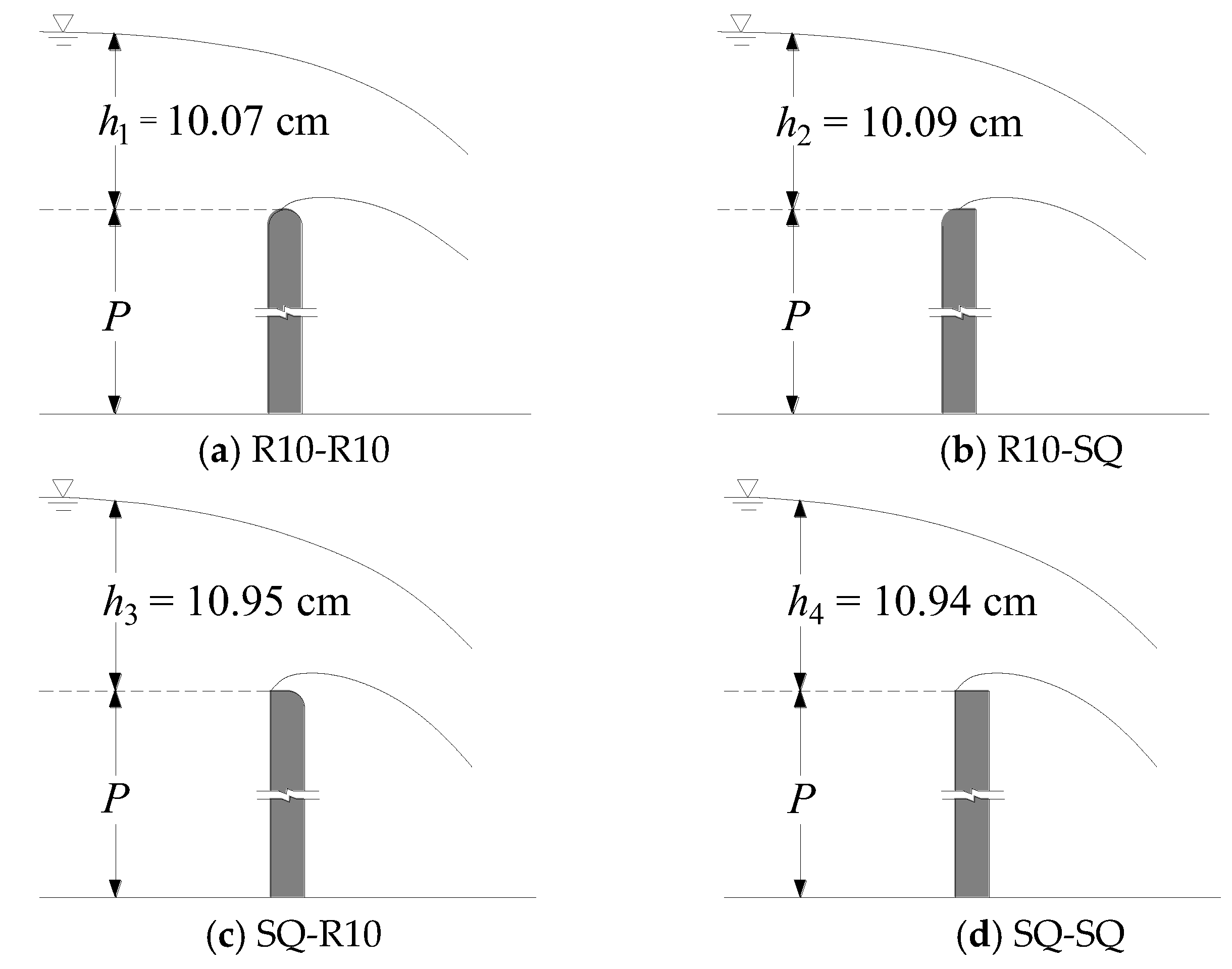
Figure 2.
Definition sketch of flow over experimental weirs (discharge is 0.036 m3/s).

Figure 3.
Variation of the detachment point for the round-crested weir: (a) Definition sketch of the distance (L) between the detachment point and upstream surface of the weir; (b) variation of L with h for weirs of different upstream corners.
Figure 3.
Variation of the detachment point for the round-crested weir: (a) Definition sketch of the distance (L) between the detachment point and upstream surface of the weir; (b) variation of L with h for weirs of different upstream corners.

Figure 4.
Head discharge relationship for weirs of different downstream corners.

Figure 5.
Variation of Cd with h for weirs of different downstream corners.

Figure 6.
Definition sketch of flow over the weir of SQ-R10: (a) Q = 0.006 m3/s; (b) Q = 0.012 m3/s.
Figure 6.
Definition sketch of flow over the weir of SQ-R10: (a) Q = 0.006 m3/s; (b) Q = 0.012 m3/s.

Figure 7.
Definition sketch of flow over the weir of SQ-SQ: (a) Q = 0.006 m3/s; (b) Q = 0.012 m3/s.

Figure 8.
Variation of Cd with h/P for the round-crested weir: five lines are drawn by the power function with different parameters for different radii of rounded upstream corners.
Figure 8.
Variation of Cd with h/P for the round-crested weir: five lines are drawn by the power function with different parameters for different radii of rounded upstream corners.

Figure 9.
Comparison of measured value to calculated value of Cd for the round-crested weir.


Table 1.
Experimental body parameters of weirs.
| Body Name | Radian of Round Upstream Corner (mm) | Radian of Round Downstream Corner (mm) | Round Radio (r/b) |
|---|---|---|---|
| R10-R10 | 10.0 | 10.0 | 1.00 |
| SQ-R10 | 0.0 | 10.0 | 0.00 |
| R10-SQ | 10.0 | 0.0 | \ |
| SQ-SQ | 0.0 | 0.0 | \ |
| R1.0-R10 | 1.0 | 10.0 | 0.10 |
| R3.0-R10 | 3.0 | 10.0 | 0.30 |
| R4.0-R10 | 4.0 | 10.0 | 0.40 |
| R5.0-R10 | 5.0 | 10.0 | 0.50 |
| R6.5-R10 | 6.5 | 10.0 | 0.65 |
| R7.5-R10 | 7.5 | 10.0 | 0.75 |
© 2019 by the authors. Licensee MDPI, Basel, Switzerland. This article is an open access article distributed under the terms and conditions of the Creative Commons Attribution (CC BY) license (http://creativecommons.org/licenses/by/4.0/).
Share and Cite
MDPI and ACS Style
Gong, J.; Deng, J.; Wei, W. Discharge Coefficient of a Round-Crested Weir. Water 2019, 11, 1206. https://doi.org/10.3390/w11061206
AMA Style
Gong J, Deng J, Wei W. Discharge Coefficient of a Round-Crested Weir. Water. 2019; 11(6):1206. https://doi.org/10.3390/w11061206
Chicago/Turabian StyleGong, Jing, Jun Deng, and Wangru Wei. 2019. "Discharge Coefficient of a Round-Crested Weir" Water 11, no. 6: 1206. https://doi.org/10.3390/w11061206
Note that from the first issue of 2016, this journal uses article numbers instead of page numbers. See further details here.