Cool Steam Method for Desalinating Seawater
by
 ,
,
Pedro Antonio Arnau
1,* ,
,
Naeria Navarro
2,
Javier Soraluce
3,
Jose María Martínez-Iglesias
2,
Jorge Illas
2 and
Eugenio Oñate
1 1
The International Center for Numerical Methods in Engineering, c/ Gran Capità, s/n, 08034 Barcelona, Spain
2
Fresh Water Nature, C/Esteve Terradas, 5, 08860 Castelldefels, Barcelona, Spain
3
Cimne Tecnología, S.A., Gran Capità, s/n Edificio B0, Campus Nord UPC, 08034 Barcelona, Spain
*
Author to whom correspondence should be addressed.
Water 2019, 11(11), 2385; https://doi.org/10.3390/w11112385
Submission received: 31 August 2019
/
Revised: 24 October 2019
/
Accepted: 6 November 2019
/
Published: 14 November 2019
(This article belongs to the Special Issue Sustainable Design for Seawater Desalination)
Abstract
:Cool steam is an innovative distillation technology based on low-temperature thermal distillation (LTTD), which allows obtaining fresh water from non-safe water sources with substantially low energy consumption. LTTD consists of distilling at low temperatures by lowering the working pressure and making the most of low-grade heat sources (either natural or artificial) to evaporate water and then condensate it at a cooler heat sink. To perform the process, an external heat source is needed that provides the latent heat of evaporation and a temperature gradient to maintain the distillation cycle. Depending on the available temperature gradient, several stages can be implemented, leading to a multi-stage device. The cool steam device can thus be single or multi-stage, being raw water fed to every stage from the top and evaporated in contact with the warmer surface within the said stage. Acting as a heat carrier, the water vapor travels to the cooler surface and condensates in contact with it. The latent heat of condensation is then conducted through the conductive wall to the next stage. Net heat flux is then established from the heat source until the heat sink, allowing distilling water inside every parallel stage.
1. Introduction
In 2015, the United Nations (UN) updated the 2030 Agenda for Sustainable Development (ASD) with 17 new goals to achieve before 2030, focused on ending poverty, protecting the environment, and ensuring dignity and equality. The sixth goal in the agenda, ‘Ensure availability and sustainable management of water and sanitation for all’ [1], has become a priority since June 2018, when the “Water Action Decade” was declared by the General Assembly of UN, a global program meant to develop the strategies to achieve all water-related targets before 2030 [2]. With no minor importance for its connection to water, Goal 2 of the ASD, in particular 2.4, urges ensuring sustainable food production systems and implementing resilient agricultural practices that increase productivity and production, that help maintain ecosystems, that strengthen capacity for adaptation to climate change, extreme weather, drought, flooding, and other disasters, and that progressively improve land and soil quality.
In a parallel manner, the European Union, through the European Environment Agency (EEA), works in action plans that relate water reuse to circular economy [3,4,5]. The Mediterranean area must show accountability with this goal in the regional and sub-regional dimension, with long-term integrated transboundary partnerships that allow driving these global challenges. Challenges are intensifying, concerning the overpopulation of the Southeastern Mediterranean (SEM) region due to migratory flows, or climate change with already noticeable effects in water scarcity and increasingly frequent natural disasters [6]. The population of the Mediterranean countries is and will be highly concentrated in coastal areas in large megalopolis (approximately 200 million people in 2030 [7,8]). This concentration is already creating several environmental challenges such as (i) the salinization of coastal groundwater due to over-exploitation of coastal aquifers and (ii) the impact of direct wastewater discharge in the Mediterranean.
As the world’s population grows, water demand is rising and the need for energy for freshwater production is increasing [9]. The water withdrawal level is higher than the water replenishment rate in more locations and with increasing frequency. This is causing water shortages, higher costs for clean water, and less reliable delivery with the reality of water shutdowns for an industry becoming more frequent. Areas with rainfall in winter but dry summers combined with increased water demand in summer, which can be exacerbated in tourist destinations, creates water shortages that affect local populations, the tourist industry, and the production capacity of nearby industries. Seawater and other contaminants are seeping into aquifers and water supplies, contaminating formerly fresh water, making it necessary to be desalinated before use.
Spain is one of the European countries most sensitized by the problem of water scarcity as it shows the high dam regulation of the Mediterranean rivers. In this context of need, we started a new investigation to obtain a more environmentally sustainable desalination technology based on vacuum distillation method, capable of competing with current desalination technologies such as seawater reverse osmosis (SWRO), multi-effect distillation (MED), or multi-stage flash (MSF) [10,11,12].
2. Cool Steam Technology
Our technology, named cool steam [13,14,15,16], consists of a low-temperature distillation process (20–50 °C) that runs under near-vacuum conditions (20–100 mbar). Cool Steam (CS) can be classified as a low-temperature thermal desalination (LTTD) method. LTTD is a desalination technique that takes advantage of the fact that water evaporates at lower temperatures at low pressures, even as low as ambient temperature [17]. Most of the LTTD units in the market continuously use a vacuum system to maintain the vacuum within the system. The energy consumption, and therefore the cost of the vacuum pumps, are quite high. At the same time, they incur product losses as water vapor is removed by the vacuum pumps.
Conversely, the CS method minimizes the need for continuous vacuum application through maintaining the whole system tightness under strict sealing conditions using switches and solenoid valves. The working pressure during the process is the water vapor pressure at the corresponding working temperature and varies from 0.02 to 0.1 bar. By removing incondensable gases and keeping the system tightness, it is not necessary to activate the vacuum pump during the process. The vacuum is performed only at the start-up and is maintained throughout the process. This reduces the consumption of electrical energy and avoids the loss of water vapor and latent heat.
CS technology works by low-temperature distillation and takes advantage of a waste or green low-grade heat source to evaporate water under vacuum conditions, condensing it at a cooler spot and obtaining freshwater with enough quality and quantity. For several years, some technologies based on low-temperature distillation process that runs under near-vacuum conditions have been developed [18,19]. CS has shown to be more energy-efficient than other similar desalination technologies since it profits from pre-existing or renewal thermal sources and has a substantially lower electrical energy consumption [20,21]. Reference [20] indicates that “there are some technical concerns regarding the possible negative effect of scaling-up of the system”, such as “the difficulty to obtain initial vacuum in a very long pipe”. Furthermore, since raw water contains incondensable gases (air), the increasing contamination of the system with incondensable gases reduces the rate of condensation in the condenser, thereby lowering the energetic efficiency of the system. Reference [21] specifies “additional mechanical energy has to be expended to maintain the required vacuum and since mechanical energy is a more valuable form of energy than heat energy, it is not a thermodynamically efficient approach”. Our technology includes water degassing tanks, and this reduces the mechanical energy required for vacuum.
For its performance, CS needs two kinds of energy input: (I) Electrical energy to cover process requirements (pumping, vacuum, sensing, and control system) and (II) low-grade thermal energy to run the distillation process. The technology can also use a low-grade waste heat source from industry [22,23]. Concerning electrical energy, the electrical demand for the water desalination processes can be supplied with renewable energy (RE) as photovoltaic panels (PV) without the need for a battery, which represents an innovative route in solar powering desalination systems. The future trend is RE use as a more economical and efficient solution compatible with climate change mitigation targets [24,25,26], which includes desalination processes and big energy consumers [27]. The adaptation and implementation of RE will allow for providing CS process the required electrical energy and storage surpluses in isolated regions through the use of batteries. Thermal energy to run distillation will be harvested with solar thermal collectors. Other heat sources as composting or sludge anaerobic digestion can be used if available.
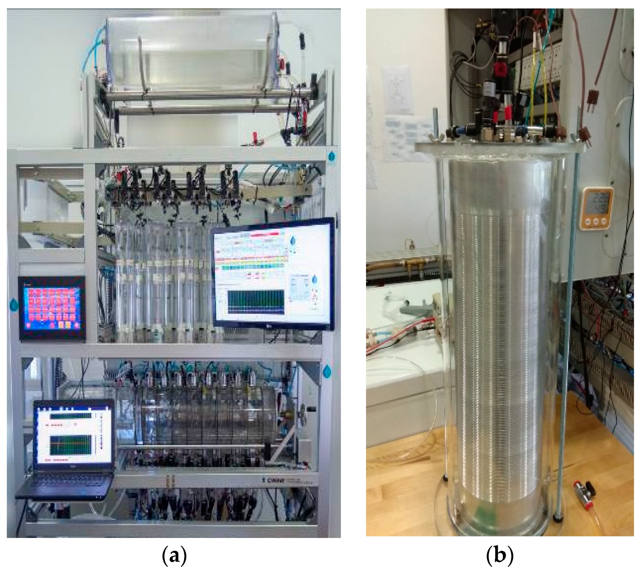
The system has single and multi-stage possible configurations (Figure 1). Single-stage is more robust, simpler, and has lower investment costs, and multi-stage enhances the process efficiency.
Apart from seawater desalination, the CS method can be applied as well to treat other water effluents, like brackish water, salinized or contaminated aquifers, wastewater from different origins, reuse of industrial process water effluents, etc.
This solution could supply water demand in arid and semi-arid areas, making the most of the surplus water recovery that was not conceived as such before (salinized water effluents, contaminated aquifers, etc.). The freshwater produced can be used to groundwater recharge. This technology may be the solution to local water scarcity and at the same time, it contributes to solving the increasing problem of wastewater effluents in a sustainable and efficient energetic way.
It would also be interesting to have a distillation system that is not necessarily associated with a power plant, that is versatile regarding both its size and its applications, and that guarantees a sustained low-density heat exchange between the heating and cooling agents.
The distillation device may comprise an evaporation part where evaporation of seawater takes place at subatmospheric pressure, to facilitate evaporation at ambient temperature and a condensation part where the water vapor condenses into freshwater. The CS device comprises at least two evaporation chambers (Figure 2), each of them delimited by two consecutive plates and entrance means to feed the evaporation chambers with seawater to be desalinated; said entrance means are suitable to feed all the evaporation chambers with seawater from a common source, for example by means of a duct connecting each evaporation chamber to a tank of de-aerated seawater. Since raw water contains incondensable gases (air), the increasing contamination of the system with incondensable gases would reduce the rate of evaporation and water vapor transport and, hence, lower the energy efficiency of the system.
With this arrangement, the entrance means are simplified, and the seawater fed to the evaporation chambers is pre-de-aerated and entered at a suitably controlled pressure and temperature that is the same for all the chambers. A suitable vacuum is created in the chambers before the operation and will be self-maintained therein when in operation.
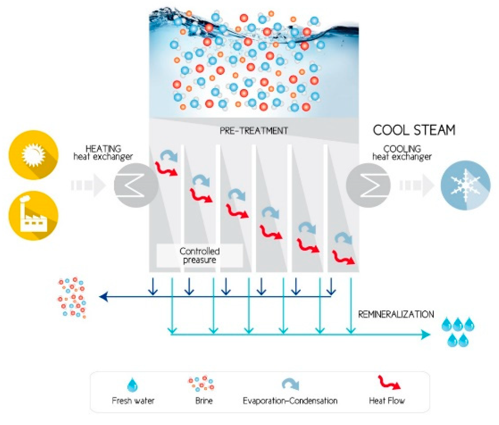
The device requires a heat flux of low thermal intensity between a hot source and a cold sink (Figure 3) and guarantees said heat flux through water vapor generation, transportation, and condensation, whereby condensed water is collected as a valuable by-product.
The system is composed of five main parts:
- Pretreatment, which is performed on all the water entering the system. It is reduced to basic primary treatment, much less strict than that required in reverse osmosis (SWRO) processes, given the delicacy of the membranes used in the latter. It will consist of roughing, flocculation, and decantation. The roughing process is the arrangement of grids and sieves for the retention of thick solids that can carry water, such as algae, crustaceans, waste, etc., thus avoiding deposits and obstructions in conduits, ensuring the proper functioning of the equipment, and improving the efficiency of the subsequent treatments. Flocculation is only necessary if seawater has a high content of colloidal matter, and in this case, the suspended organic matter and colloidal particles are eliminated, avoiding biological deposits and bacterial growth, and decreasing the biological oxygen demand (BOD) of the water. Decantation is the precipitation of solids in suspension (for example, sands or lands), as well as flocculated organic matter, which will occur in the raw water tank itself by the exclusive action of gravity. The estimated retention time is two hours, which in turn will help the water to increase its entrance temperature to the system by solar radiation.
- Water degassing tanks, at which all dissolved gases are removed from the saline water so as to not alter the vacuum generating step. This process is performed in two tanks that work alternatively. The desalination process under the CS method takes place in a tight and isolated system under vacuum. To guarantee the vacuum rate required for the process to remain self-operating, the incondensable gases dissolved in the feed water must be removed before entering the system to avoid them from hindering the water vapor transport. These incondensable gases correspond to the air dissolved in the water.
The solubility of gases in seawater is affected by temperature, pressure, and salinity. Said solubility is reduced by increasing the temperature (Table 1) or salinity, or by decreasing the pressure. Other influencing factors are the metabolic activity of living beings and the complex chemical balances with the chemical solutes, such as the bicarbonate ion (HCO3−). The total concentration and composition of dissolved gases are affected primarily with depth, which affects agitation, photosynthesis (limited to the superficial photic zone), and the abundance of organisms. The energy expenditure involved in increasing the temperature of large bodies of water to a temperature that allows the elimination of all dissolved gases is very large. Therefore, a physical deaeration is carried out by the reduction of the pressure of an intermediate passage chamber, in which the raw water is dispersed by showers so that the dissolved gases are desorbed and expelled.
- Mechanical feeding system based on piston push and pull mechanism for controlled dispensing of feed water. Synchronized system of pistons that allow volumetric control. We have designed a system of volumetric control of liquids, with two pistons controlled by electromechanical linear actuators that would drain and fill and simultaneously, to induce calibrated flow streams under vacuum conditions. To ensure smooth operation at pressures near-vacuum, the whole system would be isolated in a chamber at the same pressure as the one at the liquid source chamber.
- Multi-stage vacuum distillation core, which is composed of several chambers separated through metallic heat transfer barrier. The multi-stage cool steam distillation core is a consecution of evaporation–condensation chambers placed in series but fed in parallel. Some stages can be implemented depending on the overall available temperature gradient. As a result, there is a net heat flux between the heat source and the sink. Water vapor acts as a heat carrier. There is no mass exchange between stages and latent heat transmits from one stage to the next one by conduction through thin metal walls. Within each stage, seawater is fed from the top and is evaporated in contact with the warmer surface. This water vapor travels to the cooler surface and condensates in contact with it. The latent heat of condensation is then conducted through the wall to the next stage. As a result, two different streams are obtained: Reject (non-evaporated feed water) and distilled water (condensed water vapor).
- Fresh water and brine discharge system, which are outlet means for final extraction from the vacuum system: Self-controlled gates for outgoing batches to drain reject and distillate from the vacuum chamber (avoiding water vapor losses) and two paired floodgates that work alternatively to ensure the steady-state performance of the distillation core and vacuum keeping within it.
3. Main Results of Cool Steam Technology: Methods and Equipment Description
3.1. Equipment Description
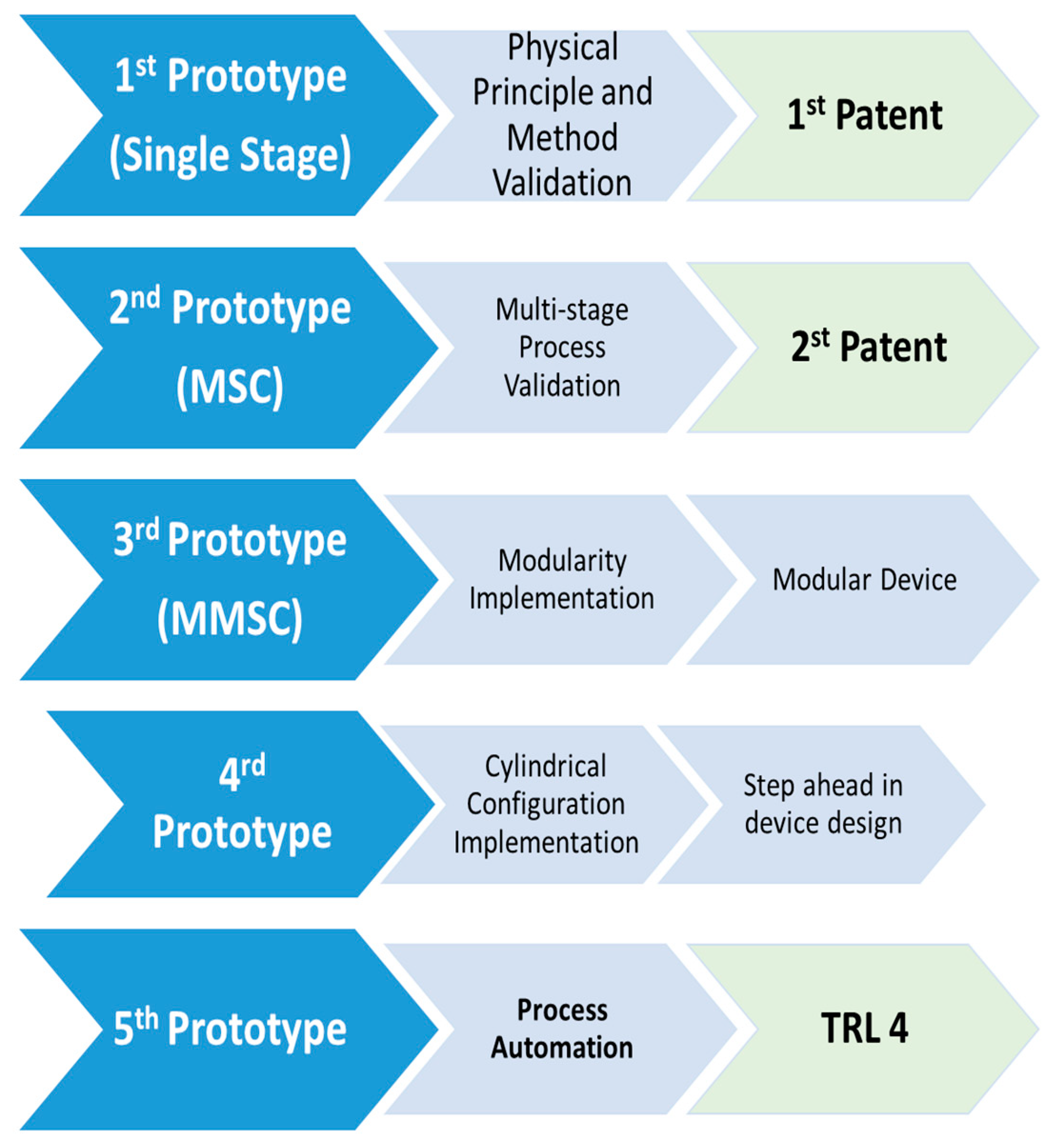
The following laboratory prototypes have been designed, built, and tested to develop the CS desalination technology during recent years (Figure 4):
(1) Single-stage prototype;
(2) Basic multi-stage prototype;
(3) Modular multi-stage prototype (proof of concept);
(4) Bigger scale and highly sensor-equipped modular multi-stage prototype;
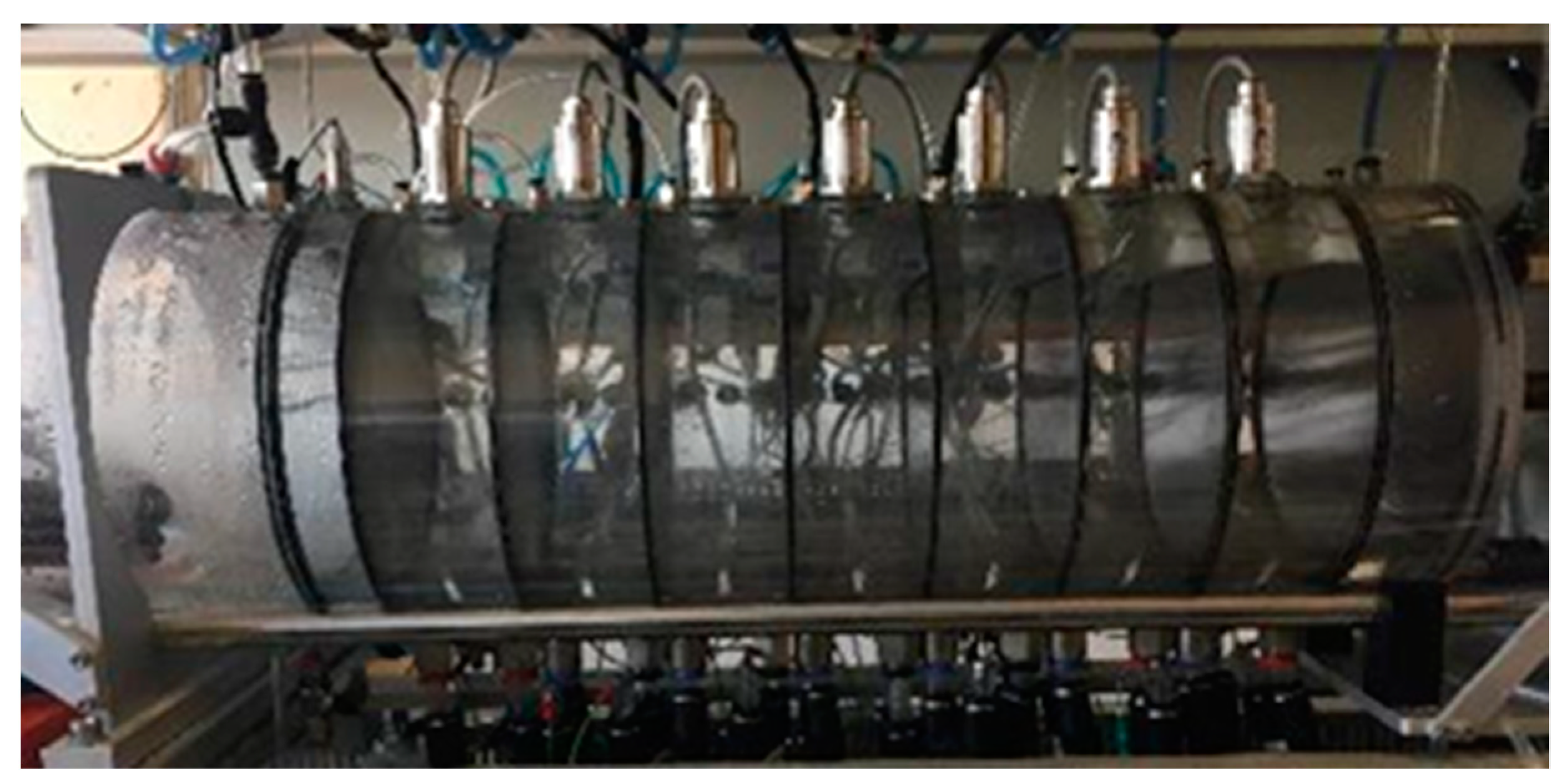
(5) Current concentric configuration prototype (proof of concept).
In the section dedicated to energy, reference is made to the different equipment used to calculate it. The desalinated water production rate of these prototypes varies between 0.1 and 4 L/h, depending on each device size and capacity. To check desalinated water quality, pH and electrical conductivity (mS/cm) are measured in the laboratory during test performance. To further water quality analysis, samples are sent to an analytical laboratory to check desalinated water suitability for drinking purposes according to standards of Spanish law, which establishes the sanitary criteria of the quality of water for human consumption. The conductivity of desalinated water by CS method varies from 600 and 1500 mS/cm (the Spanish law specification is 2500 mS/cm). Operation costs of the CS method vary from 1 and 1.2 kWh/m3 of desalinated water (kWh charging depends on the target country).
3.2. Basic Comparisons
The cool steam (CS) process is more sustainable than SWRO, MED, and MSF, as was the objective for this study. The main differences between the technologies:
1. Working temperature:
- MED between 70–40 °C;
- MSF below 120 °C;
- CS between 20–50 °C:
- Reduces scaling problems:
- CaSO4 precipitates at temperatures over 120 °C;
- CaCO3 and MgOH precipitate at alkaline pHs.
2. Heat source:
- MED and MSF need medium-grade heat (100–400 °C) provided in the form of compressed steam (generated in a boiler or from any waste heat source);
- CS uses low-grade heat (<100 °C) from both vapor and liquid streams to perform:
- A wider range of natural/waste heat sources (once it is in enough quantity and there is an available temperature gradient).
3. Layout:
- MED and MSF have serial stages;
- CS has parallel stages;
- MED and MSF have separated evaporation/condensation chambers tubes exchangers:
- Need to pump water from one effect to the other;
- High friction losses and temperature drop;
- CS perform evaporation/condensation within each chamber:
- Reduces heat losses and pumping needs;
- More compact devices;
- CS precise high tightness level.
4. Electrical energy consumption is substantially lower than those corresponding to other desalination techniques:
- MED 2.5–3 kWh/m3;
- MSF 4–6 kWh/m3;
- RO 2.5–4 kWh/m3;
- CS 1.2 kWh/m3.
Latent heat is energy released or absorbed, by a body or a thermodynamic system, during a constant-temperature process, like a phase change, for example, from solid to liquid (heat of fusion) or from liquid to gas (heat of vaporization). It should be taken into account that this energy in the form of heat is invested in the phase change and not for an increase in temperature.
where m (kg) is the mass of the substance and L (J/Kg) is the latent heat of the substance undergoing a phase change. The latent heat of vaporization for water is equal to 2264 kJ/Kg. Drifting concerning time:
where (kg/s) is the mass flow and is the thermal power associated with the phase change.
During a boiling process, the temperature remains constant as long as there is no pressure variation. In the evaporator complex, there will be a pressure valve that allows it to be kept constant and equal to the vapor pressure associated with the boiling temperature, set for example at 30 °C (Pwater vapor at this temperature is 42.43 mbar).
On the other hand, the energy associated with a change in temperature of a certain amount of substance (without phase change) corresponds to:
where:
- Cp: Heat capacity or specific heat at constant pressure. At a temperature of 25 °C, the heat required to raise the temperature of 1 kg of water by 1 °C is 4179.6 J; that is, the specific heat of water at this temperature is 4.1796 (kJ/Kg·K). At this temperature, the Cp of air is 1.0 (kJ/Kg·K).
- T: Temperature gradient suffered.
For example, using this value of Cp, if we want to dissipate a power of 10 MW from a process that generates waste heat, we would use a heat carrier liquid (process cooling water), which reaches the CS system at an initial temperature of 42 °C and that cools to an outlet temperature of 25 °C. Thus, this water stream should have a flow rate of:
If the air was used to dissipate this same power, would be equal to 588.23 kg/s, which shows that water is much more efficient for dissipating heat than air.
This stream of water circulates through a closed circuit passing through a heat exchange system, whereby it transfers its energy directly to the first stage of the distillation core, where a flow of seawater is kept evaporating in steady-state at a constant temperature thanks to a pressure and flow control system. The energy dissipated in the first evaporation surface produces evaporation of water vapor with a mass flow:
This water vapor will condense when it reaches the condensation wall, slightly cooler than the evaporation one. On the other side of the metallic wall, another flow of seawater evaporates through of the condensation heat released at the previous stage and conducted through the thin conductive wall. This combined heat transfer process is repeated as many times as distillation stages are implemented. At the end of the process, condensation heat from the last stage is dissipated using of a cooling flow through another heat exchange system.
3.3. Energy
In terms of operating costs, these correspond to the energy expenditure intrinsic to the desalination process itself, derived from the mobilization of water, vacuum performing, control system running, and that of pretreatment to which the water must be subjected before the desalination process (including deaeration). For any desalination method, the energy consumption of water mobilization and pretreatment can be preliminarily considered the same. These aspects are relevant mainly because the reduction of energy consumed to produce freshwater is one of the most active research areas in the desalination industry [29,30,31]. Additionally, the higher the conversion ratio of the method, the lower said specific consumption will be: The CS method provides a recovery ratio up to 70% of the treated water (with recirculation), while that of reverse osmosis is around 45%. This implies that the specific cost related to mobilization and pretreatment is lower than that of the SWRO.
As mentioned before, the CS method needs both thermal and electrical energy supply to perform. The latent heat of the water is very high, so the thermal desalination methods that supply it to produce the water phase change (by fossil fuel burning, for example) imply a high energy cost (higher than the SWRO). What makes CS substantially different from the rest of the desalination methods that involve phase change is that it is exempt from providing the energy equivalent to said latent heat since any waste thermal flux is used for this purpose.
Regarding electrical energy, the expenditure associated with the SWRO process itself corresponds to the compression of the water to overcome the osmotic pressure and causes freshwater to flow through the membranes and is about 2.8 kWh/m3 of water produced. The energy consumption of CS is, however, about 1.2 kWh/m3 since it does not have to supply such amounts of energy to overcome large pressure differences of SWRO.
Thus, the electrical energy consumption of the CS desalination process is given mainly by (i) the flow of water through the secondary circuit (composed of heat supply and heat dissipation flows) that must provide/dissipate the thermal heat necessary for performing the desalination process; (ii) the initial vacuum to start the system; (iii) the deaeration process, which also refers to a pretreatment to which it must be subjected water before evaporation and can be considered part of the desalination process itself, as it is not necessary in all desalination methods; and (iv) the control system.
Regardless of the expenses associated with pretreatment, collection and mobilization of source and treated water, etc., and adding the energy costs intrinsic to CS desalination process (secondary circuit pumping costs, deaeration, initial vacuum, and regulation and control), an estimated total electrical energy consumption of around 0.876 kWh/m3 of freshwater is obtained for a 10-stage system and 1.2 kWh/m3 for a three-stage system.
(a) The water flow (Esecondary circuit pumping) to be circulated through a heat exchanger to transmit to seawater to be desalinized the thermal power necessary for its evaporation, can be easily calculated as a relation between L and Cp,
L/Cp = 541.67 (K).
This ratio establishes the flow of water to be circulated through the secondary circuit according to the desalinated water that is aimed to produce. Depending on the available margin to cool down said water stream that provides the heat, the proportion between this water and the water to be desalinated flow rates varies. For example, if we can cool down the water 6 K in the secondary circuit, a flow rate about 100 times greater than the evaporated one is needed. If, on the contrary, we can cool it 60 K down, a secondary flow 10 times greater than the evaporated one is needed.
In the cold source, there will be an equivalent circuit to dissipate an equivalent amount of heat, so the energy consumption associated with the pumping of this water through the corresponding heat exchanger will be the same as that of the hot source.
We can calculate the Ehot source pumping as:
To make these previous projection calculations of a pre-industrial pilot plant, a centrifugal pump (model TP-50/30-4 of commercial brand Grundfos, https://es.grundfos.com/) was considered that drives a flow of 9 m3/h at a maximum height of 2 m, with a power of 250 W.
For the sizing of the secondary circuit of the hot spotlight, it has been taken into account that for the two phases of the project (ship and regasification plant), the water that circulates through it can be cooled to 20 K, so it would have to be pumped at the right rate of 27:1 (secondary/primary).
Considering the specifications of the pump and the available ΔT of 20 K, it is extracted that Ehot_source_pumping is 0.75 kWh/m3. This value is a function of the cooling range of the secondary water and the selected pump. The higher the production flow rates per stage, the greater the need for pumping in the secondary, the greater the number of pumps required in parallel (or more powerful pumps) and, therefore, greater specific consumption.
To reduce this specific energy consumption, the number of stages of the desalination system can be increased as much as the thermal gradient allows and the equilibrium investment/operation costs are feasible (Figure 5). The total energy consumption of the secondary circuits pumping is 1.5 kWh/m3 of treated water. In a 10-stage system, that reuses 10 times the heat supplied by the hot source to produce more water, this consumption would be 0.15 kWh/m3 treated in total. For a simplified system with a 3-stage system, the energy consumption would be 0.5 kWh/m3.
(b) The energy expenditure of the initial vacuum (Einitial vacuum), depends on the volume of the system to be emptied. The initial consumption of vacuum performance is higher since it implies more air to move and of greater density. When the system is already at low pressures, this consumption decreases and depends on the minimum pressure to be reached and the tightness of the system. For the system start-up, if its volume is large, the combination of centralized systems and local pumps can be used. The energy consumption for an initial vacuum application is negligible when compared to other energy consumptions and is calculated as:
Depending on the volume to be emptied, the initial consumption is greater, since it implies more air to be displaced and of greater density. When there is already a low pressure in the system, the consumption drops and depends on the minimum pressure that can be reached and the tightness of the system. For the startup of the system, if the volume of the system is large, the combination of centralized systems and local pumps can be used. To maintain the vacuum of the system during operation, if necessary, it will be sufficient to reconnect the local vacuum pumps.
For the calculation of the air evacuation consumption of the system designed for this project, only the use of local vacuum pumps has been determined. The prototype designed for this project has a total volume of about 500 L.
Putting this system in a vacuum for startup, once a day, has an initial energy consumption of 0.046 kWh/m3, considering a 660 W vacuum pump that evacuates at a rate of 9 m3/h. The energy consumption for the maintenance of the vacuum of the system has been calculated. Considering a once-an-hour connection of the vacuum pump to a portion of the system volume (to extract outgoing streams), we obtain a consumption of 0.033 kWh/m3.
(c) By reducing the pressure, the water desorbs the dissolved air. It can be considered that the volume of air (incondensable gases) that has returned to the gas phase is decompressed isothermally to the absolute vacuum pressure to be reached. The energy expenditure of the deaeration process (Edeaeration) can be calculated as:
The energy expenditure associated with the deaeration of the water to be desalinated has been calculated for the most probable thermal assumptions; that is, for a seawater collection temperature ranging between 0 and 30 °C, taking into account the amount of air dissolved in the water at those temperatures. A vacuum pump of 15,000 W has been used for this, which evacuates at a rate of 500 m3/h. Calculations made for smaller pumps such as those used in the laboratory are not far from these.
With the next table (Table 2) it is possible to verify that the energy consumption implied by this deaeration process is a maximum of 0.68 kWh/m3 of fed water for the most stringent conditions (at a temperature of 0 °C and a vacuum quality of 1 mbar). Under normal working conditions, the water will be collected at about 25 °C and a vacuum of 2 mbar will be more than enough to carry out the process with satisfactory performance. In such circumstances, the energy consumption of the deaeration will be 0.2 kWh/m3 fed water. Taking into account that the optimal conversion ratio is approximately 60% and all water fed to the system is de-aerated, the specific energy consumption of deaeration will be about 0.33 kWh/m3 of total water produced.
(d) The energy expenditure of the regulation and electronic control system (Econtrol system) can be calculated as the total power consumed by all the automatisms of the system (dosing system, solenoid valves, electronic control, PLC, and sensors). The specific energy consumption of the regulation and electronic control system for a 10-stage system is 0.355 kWh/m3.
4. Discussion
The energy cost for desalination technologies that are currently used is excessive. The main technologies used are the thermal processes (where there is a phase change) and the membrane processes. The thermal distillation processes include multistage flash distillation (MSF), multi-effect distillation (MED), and vapor compression (VC). The membrane processes include reverse osmosis (SWRO) and electrodialysis (ED). In thermal distillation processes, the heat represents the main portion of the energy input and is usually supplied to the system by several external sources (e.g., solar, waste energy, fossil fuel, nuclear) and the system needs electricity, which is mainly used to drive the system’s pumps. For membrane processes, only electricity is required as an energy input [11,12].
The energy costs of the application of CS technology are remarkably low. What makes this water treatment method one of a kind is that it consumes far less energy than other desalination methods when we can take advantage of some existing thermal gradient (1.2 kWh/m3 versus, for example, the 2.8 kWh/m3 of SWRO). We can use the solar thermal energy as a heat source and the dry wind or the low night temperatures as a cold source.
CS technology has no sophisticated devices involved. By not using membranes in the desalination process, there is no risk of membrane fouling. Given these features, in addition to its low energy costs, long-term application and sustained use may be assured. This aspect is a priority for its application in facilities in arid and semi-arid regions. The successful deployment of the technology would allow for making the best of dismissed salinized aquifers by a low energy consumption treatment.
For large-scale applications (>5000 m3/d), the desalination market is well consolidated. SWRO is at the forefront of the desalination market worldwide. Among all existing technologies, it has lower energy requirements. Nevertheless, it consumes huge amounts of energy to separate salt from water so that it becomes potable. Although it is, nowadays, the most extended desalination technology, principal players in the market are beginning to realize that they cannot hold it up much longer, since it is mainly run by fossil fuels. Also, these systems have not been adapted to rural regions or for decentralized operation because of their requirement for qualified and ongoing maintenance, high capital costs, and high infrastructure costs, particularly their high electrical demand. Conventional, even very modern, desalination systems are energy-intensive with energy costs. As fossil fuel prices have risen in the last years, the operational costs of producing clean water are rising and, in some cases, businesses and communities can no longer afford to run the equipment.
For small-scale applications, for example, a 100 m3/d system can provide enough clean water for the daily needs of a village with a population of about 2000 (assuming 50 liters per person per day). These villages need water for drinking, living, and basic agricultural purposes. Previously, the small-scale autonomous desalination market had been largely lost as the technology was too costly without the benefit of economies of scale. However, in the next years, the demand for solutions of autonomous desalination systems based on RE will grow, combined with electrical energy storage devices to ensure the continuity of the process during day and night [32,33]. The CS approach enables the system to operate reliably and efficiently in rural environments completely off-grid or those receiving electricity discontinuously and supplementing their production with expensive generator power. In these areas, it will be interesting to have a desalination system that is not necessarily associated to a power plant, easily scalable, capable to operate autonomously, and not vulnerable to frequent power shutdowns, with high quality water output, with low total cost of ownership and operation costs, environmental friendliness, and a long useful life with no or low performance degradation over the years.
The CS deployment is simple and consists of the design and construction of small-scale industrial distillation plants, according to the results and based on the conclusions of the previous studies. These plants would be robust, and it would contain much fewer sensors than the laboratory prototype. The features of this small-scale industrial system are specific according to the needs, but the basic characteristics is those of a system with basic water pre-treatment, at least two stages (in function of thermal gradient available), simple and robust, built-in stainless steel, production of at least 0.4 m3/h with heat supplied by sun or waste heat source, and using, for example, seawater or wind (by evaporative cooling) as cold source, and basic water post-treatment (remineralization).
5. Conclusions
The most transcendental impact that the successful deployment of the proposed technology will produce is the reduction in more than 50% of energy demand in water desalination. Although the energy cost of supply and transportation will be the same for given amounts of treated water, the treatment process itself will be significantly less energy-intensive concerning other desalination systems. The cool steam technology reaches high desalination efficiency ratios with a substantially low energy consumption associated using waste heat. The proposed solution will allow for providing efficiently fresh water to small communities in isolated regions, which will, therefore, reduce total costs and will contribute to guarantee water availability. In turn, it implies a substantial reduction in CO2 emissions, since for every kWh saved, the emission of CO2 into the atmosphere is avoided. This also implies a strategic environmental advantage over other desalination techniques.
6. Patents
Next, we show the validated patents resulting from the work reported in this manuscript:
- Device, apparatus, and method for desalinating seawater, Arnau del Amo, Pedro Antonio, Oñate Ibáñez de Navarra, Eugenio, Hanganu, Dan Alexandru and Navarro Navarro, Naeria. European Patent Office. Espacenet. Application number: EP2013038219620130528. Publication date: 2014-12-4.
- System and method for desalinating seawater, Arnau del Amo, Pedro Antonio, Oñate Ibáñez de Navarra, Eugenio, Hanganu, Alex. European Patent Office. Espacenet, Application num: EP2011038219820110615. Publication date: 2012-12-19.
- System and method for desalinating seawater Arnau del Amo, Pedro Antonio, Oñate Ibáñez de Navarra, Eugenio, Hanganu, Dan Alexandru. Saudi Arabia/GCC, National Phase. Application number: 112 33 0608. Publication date: 2012-6-11.
- Device, apparatus and method for desalinating seawater, Arnau del Amo, Pedro Antonio, Oñate Ibáñez de Navarra, Eugenio, Hanganu, Dan Alexandru and Navarro Navarro, Naeria. US, National Phase. Application number: 10315932. Publication date: 2019-6-11.
Author Contributions
N.N., E.O. and P.A.A. have researched y developed the technology from the beginning, including conceptualization, methodology development, collecting the data, implementing the energy system, generating and analyzing the results. N.N., J.S., J.M.M.-I., and J.I. did the development of software, the main task of laboratory for the prototype construction in the last years and their validation. J.S. and N.N. visualized and developed the figures. P.A.A. and E.O. obtain funds from research projects. N.N. and P.A.A. have the supervision and the project administration, they wrote the original manuscript, their review, and editing, framed the research questions and scope of the work, checked the results, facilitated discussions, and reviewed the manuscript.
Funding
This research was funded by Agència de Gestió d’Ajuts Universitaris i de Recerca (2014 PROD 00086) |Ministerio de Economía y Competitividad (RTC-2015-3994-2; RTC-2017-6711-2)| and for European Commission (ERANet17/ERY-0168).
Acknowledgments
The authors are grateful for the acknowledge offered by Francesc Campá, Francesco Cristiano, Stefano Fava, Alexandru Dan Hanganu, Ignacio Valero and Jordi Jiménez, as well as for their technical support in the initial tasks of research.
Conflicts of Interest
The authors declare no conflict of interest. The founding sponsors had no role in the design of the study; in the collection, analyses, or interpretation of data; in the writing of the manuscript, and in the decision to publish the results.
Abbreviations
| ASD | Agenda for Sustainable Development |
| BOD | Biological Oxygen Demand |
| CS | Cool Steam |
| EEA | European Environment Agency |
| ED | Electrodialysis |
| LTTD | Low-temperature thermal distillation |
| MSF | Multi-Stage Flash |
| MED | Multi-Effect Distillation |
| OTEC | Ocean Thermal Energy Conversion |
| PV | Photovoltaic |
| RE | Renewable Energy |
| SEM | South-Eastern Mediterranean |
| SWRO | Seawater Reverse Osmosis |
| UN | United Nations |
| VC | Vapor Compression |
| WHO | World Health Organization |
References
- United Nations. Transforming our World: The 2030 Agenda for Sustainable Development; United Nations: New York, NY, USA, 2015. [Google Scholar]
- United Nations. International Decade for Action, Water for Sustainable Development, 2018–2028; United Nations: New York, NY, USA, 2016. [Google Scholar]
- Mangion, J.; Mundo, F.; Puig, A.; Antolin, M.; Zacharian, M.; Eliades, P.; Duchemin, J.; Nasser Al Abdel-Shafy, H.; Abu Awwad, A.; Mohammed, A.; et al. Mediterranean Wastewater Reuse Report. Mediterranean Wastewater Reuse Working Group, EC, 2007. Available online: https://ec.europa.eu/environment/water/blueprint/pdf/med_final_report.pdf (accessed on 13 November 2019).
- Kirhensteine, I.; Cherrier, V.; Jarritt, N.; Farmer, A.; de Paoli, G.; Delacamara, G.; Psomas, A. EU-Level Instruments on Water Reuse; Amec Foster Wheeler Environment & Infrastructure UK Ltd., IEEP, ACTeon, IMDEA and NTUA: Luxembourg, 2016; ISBN 978-92-79-62616-6. [Google Scholar]
- Hochstrat, R.; Joksimovic, D.; Wintgens, T.; Melin, D.; Savic, D. Economic considerations and decision support tool for wastewater reuse scheme planning. Water Sci. Technol. 2007, 56, 175–182. [Google Scholar] [CrossRef] [PubMed]
- Cramer, W.; Guiot, J.; Fader, M.; Garrabou, J.; Gattuso, J.-P.; Iglesias, A.; Lange, M.A.; Lionello, P.; Llasat, M.C.; Paz, S.; et al. Climate change and interconnected risks to sustainable development in the Mediterranean. Nat. Clim. Chang. 2018, 8, 972–980. [Google Scholar] [CrossRef]
- Plan, B. A Sustainable Future for the Mediterranean: The Blue Plan’s Environment and Development Outlook; Benoit, G., Comeau, A., Eds.; Chapter on “Coastal Areas”; Earthscan: London, UK, 2005; pp. 303–356. [Google Scholar]
- United Nations. Probabilistic Population Projections Based on the World Population Prospects: The 2015 Revision; Population Division; United Nations Department of Economic and Social Affairs (DESA): New York, NY, USA, 2015; Available online: http://esa.un.org/unpd/ppp/ (accessed on 13 November 2019).
- United Nations World Water Assessment Programme. The United Nations World Water Development Report 2014: Water and Energy; The United Nations Educational, Scientific and Cultural Organization (UNESCO): Paris, France, 2014; Available online: http://unesdoc.unesco.org/images/0022/002257/225741E.pdf (accessed on 13 November 2019).
- Mehzer, T.; Fath, H.; Abbas, Z.; Khaled, A. Techno-economic assessment and environmental impacts of desalination technologies. Desalination 2011, 266, 263–273. [Google Scholar]
- Al-Kharaghouli, A.; Kazmerski, L.L. Energy consumption and water production cost of renewable energy powered desalination processes. Renew. Sustain. Energy Rev. 2013, 24, 343–356. [Google Scholar] [CrossRef]
- Alkaisia, A.; Mossadb, R.; Sharifian-Barforoush, A. A review of the water desalination systems integrated with renewable energy. Energy Procedia 2017, 110, 268–274. [Google Scholar] [CrossRef]
- Arnau del Amo, P.A.; Oñate Ibáñez de Navarra, E.; Hanganu, D.A. System and Method for Desalinating Seawater. European Patent Office, Espacenet Application No. EP2,011,038,219,820,110,615, 19 December 2012. Available online: https://worldwide.espacenet.com/publicationDetails/biblio?DB=EPODOC&II=1&ND=3&adjacent=true&locale=en_EP&FT=D&date=20160505&CC=US&NR=2016122205A1&KC=A1#?locale=en_EP&II=0&date=20170426&CC=CY&NR=1117333T1&ND=3&KC=T1&rnd=1546855789713&adjacent=true&FT=D&DB=EPODOC (accessed on 26 April 2017).
- Arnau del Amo, P.A.; Oñate Ibáñez de Navarra, E.; Hanganu, D.A. System and Method for Desalinating Seawater. Saudi Arabia/GCC, National Phase Application No. 112,330,608, 6 November 2012. [Google Scholar]
- Arnau del Amo, P.A.; Oñate Ibáñez de Navarra, E.; Hanganu, D.A.; Navarro Navarro, N. Device, Apparatus and Method for Desalinating Seawater. European Patent Office, Espacenet Application No. EP2,013,038,219,620,130,528, 4 December 2014. Available online: https://worldwide.espacenet.com/publicationDetails/biblio?DB=EPODOC&II=1&ND=3&adjacent=true&locale=en_EP&FT=D&date=20160505&CC=US&NR=2016122205A1&KC=A1 (accessed on 5 May 2016).
- Arnau del Amo, P.A.; Oñate Ibáñez de Navarra, E.; Hanganu, D.A.; Navarro Navarro, N. Device, Apparatus and Method for Desalinating Seawater. U.S. Patent Application No. US10,315,932 B2, 11 June 2019. Available online: http://patft.uspto.gov/netacgi/nph-Parser?Sect1=PTO1&Sect2=HITOFF&p=1&u=/netahtml/PTO/srchnum.html&r=1&f=G&l=50&d=PALL&s1=10315932.PN (accessed on 11 June 2019).
- Rognoni, M.; Kathiroli, S.; Jalihal, P. Low Temperature Thermal Desalination (LTTD): New sustainable desalination process. Int. J. Nucl. Desalin. 2008, 3, 69–78. [Google Scholar] [CrossRef]
- Akers, J.N. Multi-Stage Water Distilling Apparatus. U.S. Patent O 3,275,530, 27 September 1966. [Google Scholar]
- Petrek, J.P.; Cantrell, C.M. Multiple Effect Thin Film Distillation System and Process. U.S. Patent US4402793A, 6 September 1983. [Google Scholar]
- Inoue, K.; Abe, Y.; Murakami, M.; Mori, T. Feasibility study of desalination technology utilizing the temperature difference between seawater and inland atmosphere. Desalination 2006, 197, 137–153. [Google Scholar] [CrossRef]
- Gude, G.V.; Nirmalakhandan, N. Desalination at low temperatures and low pressures. Desalination 2009, 244, 239–247. [Google Scholar] [CrossRef]
- Ling-Chin, J.; Bao, H.; Ma, Z.; Taylor, W.; Roskilly, A.P. State-of-the-Art Technologies on Low-Grade Heat Recovery and Utilization in Industry. In Energy Convers—Current Technologies and Future Trends; Al-Bahadly, I.H., Ed.; IntechOpen: London, UK; Available online: https://www.intechopen.com/books/energy-conversion-current-technologies-and-future-trends/state-of-the-art-technologies-on-low-grade-heat-recovery-and-utilization-in-industry (accessed on 5 November 2018). [CrossRef]
- Kishore, R.A.; Priya, S. A Review on Low-Grade Thermal Energy Harvesting: Materials, Methods and Device. Materials 2018, 11, 1433. [Google Scholar] [CrossRef] [PubMed]
- Aghahosseini, A.; Bogdanov, D.; Ghorbani, N.; Breyer, C. The role of a 100% renewable energy system for the future of Iran: Integrating solar PV, wind energy, hydropower and storage. In Proceedings of the 11th International Renewable Energy Storage Conference, Düsseldorf, Germany, 14–16 March 2017. [Google Scholar]
- Barbosa, L.S.N.S.; Bogdanov, D.; Vainikka, P.; Breyer, C. Hydro, wind and solar power as a base for a 100%Renewable Energy supply for South and Central America. PLoS ONE 2017, 12, e173820. [Google Scholar] [CrossRef] [PubMed]
- Child, M.; Bogdanov, D.; Breyer, C. The role of storage technologies for the transition to a 100% renewable energy system in Europe. Energy Procedia 2018, 155, 44–60. [Google Scholar] [CrossRef]
- Caldera, U.; Bogdanov, D.; Breyer, C. Local cost of seawater RO desalination based on solar PV and wind energy: A global estimate. Desalination 2016, 385, 207–216. [Google Scholar] [CrossRef]
- Libes, S.M. An Introduction to Marine Biogeochemistry; John Wiley & Sons: Hoboken, NJ, USA, 1992. [Google Scholar]
- Reddy, K.V.; Ghaffour, N. Overview of the cost of desalinated water and costing methodologies. Desalination 2007, 205, 340–353. [Google Scholar] [CrossRef]
- Al-Zahrani, A.; Orfi, J.; Al-Suhaibani, Z.; Salim, B.; Al-Ansary, H. Thermodynamic analysis of a reverse osmosis desalination unit with energy recovery system. Procedia Eng. 2012, 33, 404–414. [Google Scholar] [CrossRef]
- Loutatidou, S.; Chalermthai, B.; Marpu, P.R.; Arafat, H. Capital cost estimation of RO plants: GCC countries versus southern Europe. Desalination 2014, 347, 103–111. [Google Scholar] [CrossRef]
- Kittner, N.; Lill, F.; Kammen, M.D. Energy storage deployment and innovation for the clean energy transition. Nat. Energy 2017, 2, 17125. [Google Scholar] [CrossRef]
- Schmidt, O.; Hawkes, A.; Gambhir, A.; Staffell, I. The future cost of electrical energy storage based on experience rates. Nat. Energy 2017, 2, 17110. [Google Scholar] [CrossRef]
Figure 1.
Cool steam laboratory prototypes: Multi-stage device (a) and single-stage concentric device (b).
Figure 1.
Cool steam laboratory prototypes: Multi-stage device (a) and single-stage concentric device (b).

Figure 2.
Multi-stage cool steam device basic configuration.

Figure 3.
Preliminary experimental cool steam test.

Figure 4.
Laboratory prototypes evolution.

Figure 5.
Multi-stage vacuum distillation: Continuous reuse of latent heat of evaporation.


Table 1.
Gas content in seawater in atmospheric equilibrium [28].
Table 1.
Gas content in seawater in atmospheric equilibrium [28].
| T (°C) | Pv, H2O (mbar) | N2 CN2 (mmol/m3) | O2 CO2 (mmol/m3) | CO2 CCO2 (mmol/m3) | Ar CAr (mmol/m3) |
|---|---|---|---|---|---|
| 0 | 6.09 | 636 | 356 | 23.4 | 17.0 |
| 5 | 8.70 | 566 | 313 | 19.3 | 15.0 |
| 10 | 12.26 | 508 | 279 | 16.1 | 13.3 |
| 15 | 17.04 | 461 | 250 | 13.6 | 12.0 |
| 20 | 23.37 | 420 | 226 | 11.6 | 10.8 |
| 25 | 31.67 | 386 | 205 | 10 | 9.81 |
| 30 | 42.43 | 355 | 187 | 8.66 | 8.93 |
Table 2.
Energy consumption per m3 of treated water for different vacuum qualities.
| T (°C) | Pv,H2O (mbar) | 1 mbar E (kWh /m3) | 2 mbar E (kWh /m3) | 5 mbar E (kWh /m3) | 10 mbar E (kWh /m3) |
|---|---|---|---|---|---|
| 0 | 6.09 | 0.68 | 0.34 | 0.14 | 0.07 |
| 5 | 8.70 | 0.61 | 0.30 | 0.12 | 0.06 |
| 10 | 12.26 | 0.54 | 0.27 | 0.11 | 0.05 |
| 15 | 17.04 | 0.49 | 0.24 | 0.10 | 0.05 |
| 20 | 23.37 | 0.44 | 0.22 | 0.09 | 0.04 |
| 25 | 31.67 | 0.41 | 0.20 | 0.08 | 0.04 |
| 30 | 42.43 | 0.37 | 0.19 | 0.07 | 0.04 |
© 2019 by the authors. Licensee MDPI, Basel, Switzerland. This article is an open access article distributed under the terms and conditions of the Creative Commons Attribution (CC BY) license (http://creativecommons.org/licenses/by/4.0/).
Share and Cite
MDPI and ACS Style
Arnau, P.A.; Navarro, N.; Soraluce, J.; Martínez-Iglesias, J.M.; Illas, J.; Oñate, E. Cool Steam Method for Desalinating Seawater. Water 2019, 11, 2385. https://doi.org/10.3390/w11112385
AMA Style
Arnau PA, Navarro N, Soraluce J, Martínez-Iglesias JM, Illas J, Oñate E. Cool Steam Method for Desalinating Seawater. Water. 2019; 11(11):2385. https://doi.org/10.3390/w11112385
Chicago/Turabian StyleArnau, Pedro Antonio, Naeria Navarro, Javier Soraluce, Jose María Martínez-Iglesias, Jorge Illas, and Eugenio Oñate. 2019. "Cool Steam Method for Desalinating Seawater" Water 11, no. 11: 2385. https://doi.org/10.3390/w11112385
Note that from the first issue of 2016, this journal uses article numbers instead of page numbers. See further details here.