Mathematical Modeling of Ice Thrusting on the Shore of the Vistula Lagoon (Baltic Sea) and the Proposed Artificial Island


Faculty of Civil and Environmental Engineering, Gdańsk University of Technology, Narutowicza 11/12, 80-233 Gdańsk, Poland
*
Author to whom correspondence should be addressed.
Water 2019, 11(11), 2297; https://doi.org/10.3390/w11112297
Submission received: 4 October 2019
/
Revised: 29 October 2019
/
Accepted: 31 October 2019
/
Published: 2 November 2019
(This article belongs to the Special Issue Modeling and Analysis of Hydrodynamics, Water Quality and Ice Phenomena for Lagoons and Shallow Bays)
Abstract
:Coastal lagoons are inland and shallow water bodies, separated from the ocean by a barrier. In cold regions, ice phenomena in shallow water coastal lagoons occur every winter season. Ice is predominantly formed on the surface due to density stratification and surface cooling. The ice dynamics in such areas are dominantly affected by winds. Water dynamics also cause ice movement, but due to the large areal scale of lagoons, the effect is usually limited to the direct vicinity of river estuaries. For open lagoons, which are connected to the sea by straits, tides will also cause significant movement of the ice inside the lagoon. Due to the limitation of ice outflow from a lagoon, ice fields will form ridges or hummocks on the shores. In this paper, the case of the Vistula Lagoon, located on the southern Baltic coast, is analyzed. Currently, the project of a new strait connecting the Baltic Sea with the Vistula Lagoon is in progress. As an effect of extensive dredging for the waterway to the port of Elblag, the material will be disposed of at a Confined Disposal Facility (CDF), which will form an artificial island. The island will be located on the western part of the lagoon, limiting the cross-section by about 20%. In consequence, ice cover pushed by winds blowing along the lagoon will create significant force action on the island banks. The DynaRICE mathematical model has been used to evaluate the ice dynamics and to determine the force produced by the ice on the coasts of the lagoon and the artificial island.
1. Introduction
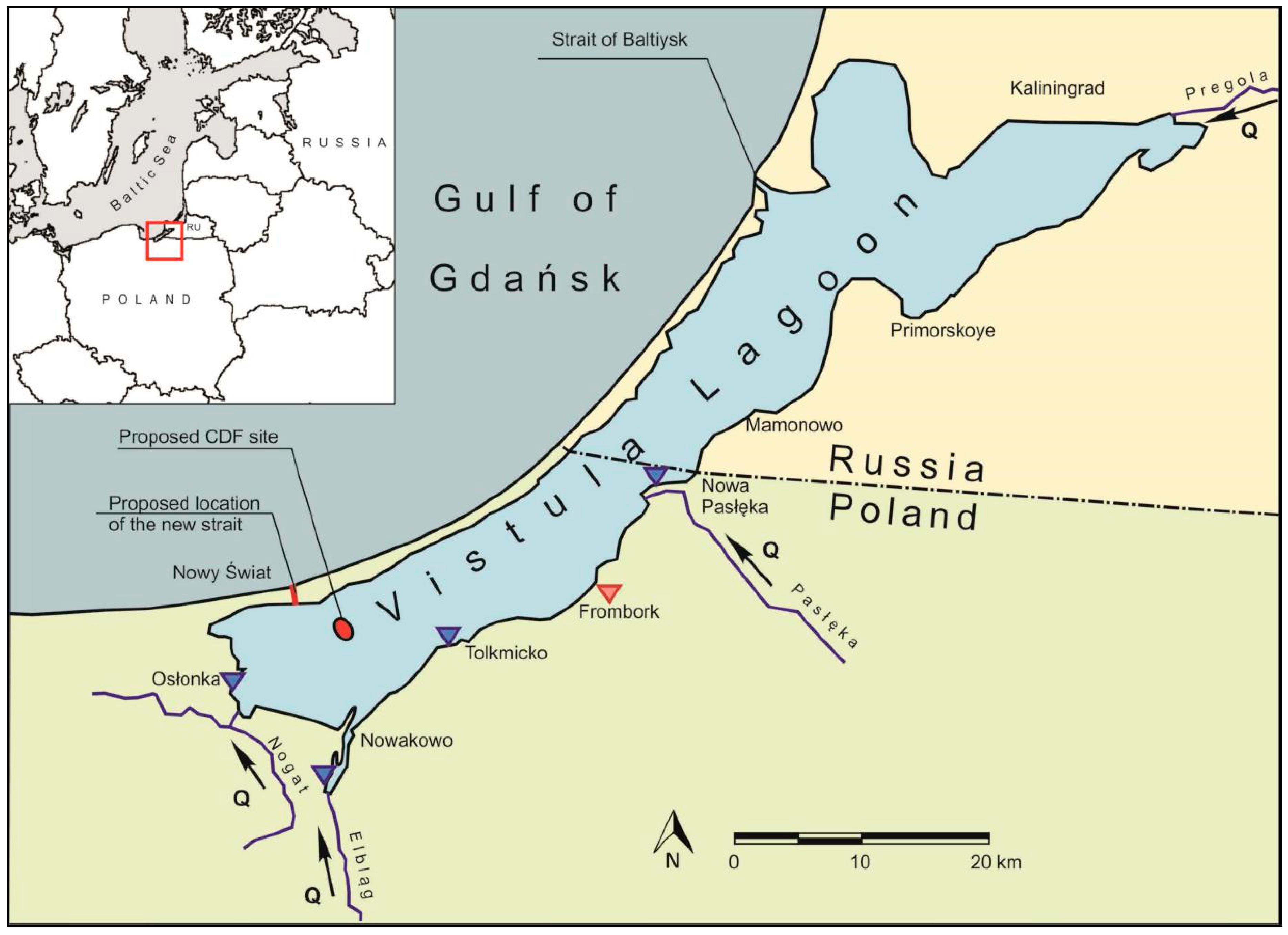
In the contact zone of sea and land waters, coastal lakes and lagoons form as a transition zone of two different water regimes. This zone constantly experiences phenomena and processes of mutual interaction. Coastal lagoons are defined in [1] as inland and shallow water bodies (of depths not exceeding a few meters), separated from the ocean by a barrier and connected to the ocean by at least one restricted inlet. A classic example of a coastal lagoon in the southern Baltic Sea is the Vistula Lagoon. In the 20th century, the Vistula Lagoon experienced major hydrological changes, in particular the reduction of its catchment area by the Vistula River basin, as a result of the Nogat being cut off by a lock near Biała Góra in 1915. Before this, the lagoon was a freshwater reservoir, constantly backfilled and shallow with Vistula sediments, and now it has turned into a saltwater reservoir. Once the huge sedimentation was interrupted, instead of the inflow of Vistula waters, Baltic water became the overwhelming factor, with an easier intrusion through the Strait of Baltijsk, which is 2 km long, 440 m wide, and approximately 8.8 m deep. The length of the lagoon is 90.7 km and its width varies from almost 6 km up to 13 km. The lagoon is a shallow basin with an average depth of only 2.75 m [2].
The largest rivers flowing into the Vistula Lagoon are: the Pregolya (providing 62% of the freshwater) and other small rivers flowing from the Russian part, and the Pasłęka, the Elbląg, the Nogat, and the Szkarpawa flowing from the Polish side, as seen in Figure 1. The inflow of fresh water from the Vistula to the lagoon, as a result of the functioning of the locks on the Nogat and the Szkarpawa, is very limited. The average annual river water inflow to the lagoon is about 100 m3·s−1. Instantaneous flows are in the range of about 40 m3·s−1 to about 1300 m3·s−1. The maximum daily changes in the water level in the lagoon caused by these inflows do not exceed 0.1 m [3].
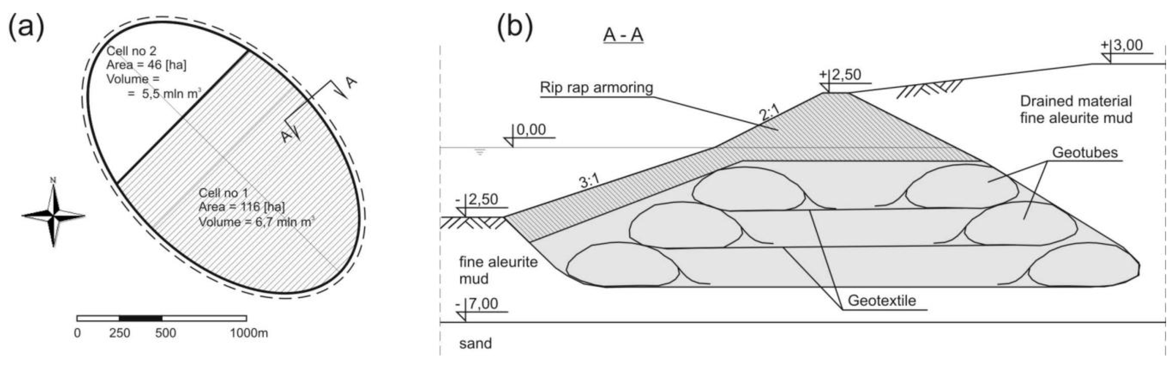
A new project is currently being implemented regarding the construction of a waterway connecting the Vistula Lagoon with the Gulf of Gdańsk. The basic elements of the waterway include the construction of a navigable canal (artificial strait) through the Vistula Spit, the construction of a fairway from the mouth of the Elbląg Bay to the channel, and a Confined Disposal Facility (CDF). In the planned CDF, dredged material will be placed behind dikes, which will contain and isolate it from the surrounding environment [4]. The type of CDF planned for the Vistula Lagoon is an island type and will be constructed offshore, but in relatively shallow water. In the CDF, a mixture of dredged material and water is pumped into an area that is divided into several smaller areas, called cells. As the water moves between the cells, it slows; the dredged material settles, and finally, clean water is discharged from the site. The proposed CDF site in the Vistula Lagoon will have a total volume of 9.2 million m3 and will consist of two separate cells which, when filled, will form an island with an area of approximately 180 ha. The island has been designed in the shape of an ellipse with its longer axis equal to 1930 m and shorter to 1190 m, as seen in Figure 2a.
The construction of the proposed CDF site consists of earth dikes with a base width of 25 m reinforced with geotextiles in Geotube technology. After the stabilization of the dike structure at the level of the load-bearing soil (sand), rip-rap armoring will be laid from the outside, forming an external slope inclined in the underwater part 3:1 and the upper part 2:1. The CDF site will be filled up to 3.0 m above sea level, as seen in Figure 2b. After completion of the filling of the island with dredging material and the stabilization of the soil (draining), it is possible to use the island for other purposes, such us a habitat improvement project (HIP) for birds, amphibians, and other aquatic species.
Ice on coastal lakes and shallow water lagoons in cold regions typically forms as a result of thermal cooling and vertical water density stratification. Such is the case when, due to a lack of turbulence and limited water velocity, the surface layer of water quickly cools and skim ice is formed [5]. If conditions are favorable, the skim ice may develop into solid, stationary ice cover, which could stretch over the entire water body. Once the cover is formed, its movement is limited by the land boundaries and the ice dynamics are usually considered as insignificant and neglected; however, mechanical ice thrusting can occur due to wind or the sea water rise effect. Tides or storm surges will obviously affect only open lagoons, which are connected to the sea by straits. Due to the limitation in displacement, ice pushed by wind or high water level in the sea will thrust against the banks or collapse and accumulate on the cracks, forming ridges. These forms are not common, but can be observed on coastal water bodies in the southern Baltic, i.e., Szczecin Lagoon or the Vistula Lagoon [6]. Piled-up ice may endanger coastal and onshore structures such as lighthouses, navigation and signal beacons, harbors or artificial islands. For hydro-engineering structures, some regulations are used to ensure materials strong enough to resist ice impact. Furthermore, the potential threat of landslides concerns the shores of the Vistula Lagoon due to the thrusting of the ice ashore. As the ice load on the shores of coastal lagoons is affected by many factors, it should be investigated further.
Ice monitoring in sheltered water bodies of the southern Baltic coast has been summarized in [7], and for the Vistula Lagoon in [8], but this only covers data from a period of the last century (from 1950 to 1990). More recent data for the winter seasons 2003/2004–2016/2017 have been presented in [9] and ice data were collected from the Swedish Meteorological Institute’s Sea Ice Service. In recent years, satellite produced images have provided information on the distribution of ice cover [10] and polynya dynamics [11] in the Vistula Lagoon and are a good complement to field measurements. Based on historical observations, the Vistula Lagoon freezes nearly every season and ice cover commonly occurs over its entire extent. During severe winters the Vistula Lagoon freezes for an average of four months. In mild winters, the Lagoon froze for no more than 2.5 months (January–March), and the ice only covered parts of the waters offshore or did not occur. The average monthly long-term minimum temperature of the lagoon waters is 0.13 °C. The thickness of the ice cover can be up to 60 cm. The disappearance of the ice cover usually occurs in March, first from the side of Żuławy and the Elbląg Upland, and then in the middle pool. The ice stays the longest in the northern Russian part of the lagoon, except for the zone at the Piławska Strait, which is affected by the warmer (on average 1–2 °C) and saltier waters of the Gulf of Gdańsk. Even though from 2003 there were five seasons without continuous ice cover on the Vistula Lagoon, there is no clear trend in the duration of the ice cover or the dates for freezing and breakup [9]. The ice phenomena on the Vistula Lagoon, understood as the probability of ice occurrence and the number of days with ice, reflect trends observed on the southern Baltic Sea, as described in [12].
Ice–shore interaction has been studied in many ways. In most cases, the structural load is determined by that required for ice failure. Thus, the common design concept is to slope the structure at the water line to induce a bending failure rather than a crushing failure. For any hydro-engineering structure subjected to ice interaction, the structural force should be analyzed with two goals: to determine the angle of the slope needed to induce a bending failure and to determine the magnitude of the loads. Since the design for the new waterway of the Vistula Lagoon is already set, all the dimensions of the artificial island will be adopted for the project and the angle of the slope will not be determined here. The magnitude of the loads on the island shore as well as on the harbor and lagoon coasts will be determined using the previously calibrated DynaRICE model [13].
2. Numerical Model
Many mathematical models of the Vistula Lagoon have been developed over the last decades, including two-dimensional (2D) hydrodynamic models [14,15,16], 2D models composed of hydrodynamics, water quality and eutrophication modules [17,18,19], and recently developed three-dimensional models used for sediment transport and migration [3,20,21]. Despite the significant number of applications of numerical models to the Vistula Lagoon, water and ice dynamics during the winter season have not been simulated.
In the current study, the ice phenomena are investigated by applying the DynaRICE two-dimensional river ice dynamic model. The model was developed at Clarkson University [5] to simulate river ice processes including ice formation and breakup [22,23,24], ice jam dynamics [22,25,26,27] and ice load determination for both vertical [28,29,30] and sloped structures [31,32]. Even though the model was primarily developed to reproduce ice dynamics in rivers, where the ice movement is mainly driven by water hydrodynamics, it has been successfully applied to a coastal lake subjected to sea tides [33].
The DynaRICE is a coupled model composed of hydrodynamics and ice dynamics solved separately. All information from each module is transferred to the other one at every coupling time step, which for this study was set to 15 min. The water hydrodynamics are calculated by solving a two-dimensional set of shallow water equations [23]:
in which water surface elevation; and are components of the total unit width of water discharge; , are components of the unit width of water discharge beneath the ice layer; and are the water discharge in the upper layer; ice concentration; ice thickness; and are generalized eddy viscosity coefficients; and are shear stresses at the ice–water interface and the river bed; and is the water depth underneath the equivalent ice–water interface and the bed.
Dynamic transport of river ice is mathematically described as the movement of the number of particles carrying all ice properties and being subjected to force balance. Considering the surface ice layer on the water surface as a continuum, the equation of motion can be derived from the momentum balance of an elemental area. The governing equation for ice dynamics can be presented in Lagrangian form as follows [34]:
where: is the unit mass (per area) of an ice particle, is the ice velocity vector, is the internal ice resistance force, and are the wind and water drag is a gravitational force due to the water surface slope. In the two-dimensional approach, the internal ice resistance force is defined in the following form [34]:
in which and are the normal internal stresses in ice rubble, and are the tangential internal ice stresses. All stresses are determined at the point where the considered ice particle is located, and the ice parcel is determined by the vector , defined as follows: . The determination of internal stresses is based on a viscoelastic-plastic constitutive model for ice dynamics, as described in [35]. Other components of Equation (4) are presented below [34]:
In the above equations, Cw (−) is the wind coefficient Cw = 0.00155 [36], ρa is the air density (kg·m−3), (m·s−1) is the water velocity vector, (m·s−1) is the surface ice velocity vector, (m·s−1) is the wind velocity vector at 10 m above the water or ice surface, is the roughness coefficient of the underside of the ice surface, (m) is the water depth, (−) is a parameter describing the proportion of the cross-section area affected by the ice only to the entire cross-section area.
Since it is impractical and not necessary to solve the governing equations for ice dynamics and hydrodynamics simultaneously, a coupled ice dynamic and hydrodynamic model with the proper time integration scheme was developed. The Finite Element Method was used to solve the hydrodynamic equations using the streamline-upwind Petrov–Galerkin weighted residual concept over triangular elements with linear shape functions [37]. The Explicit Finite Element Method was employed to integrate the equations with respect to time. The developed finite element model allows the simulation of two-dimensional transitional flows and the treatment of dry-and-wet bed conditions.
The solution to the ice dynamic equation was carried out using the Smoothed Particle Hydrodynamics (SPH) method along with images implemented to land boundaries. The method, applied to dynamic river ice processes, has been described in [38].
3. Results and Discussion
The mathematical model (1–3), solved by the described technique, was applied to simulate the unsteady water flow and ice dynamics in the Vistula Lagoon. To include the inflow and outflow effect from the Baltic Sea, the model domain was extended about 50 km into Gulf of Gdańsk, where water surface elevation (WSE) boundary conditions were set up. The freshwater inflow to the model domain was implemented at four locations, representing the four main rivers discharging into the Vistula Lagoon. In these locations, as indicated by red arrows in Figure 3, open boundaries were set in the form of water discharge conditions. Since no data on Russian rivers were available, only the discharge from the Pregolya was included in the model. On the Polish side of the lagoon, the Paslęka, the Elbląg, and the Nogat (including the Szarpawa) were simulated. The initial conditions were obtained from simulations of the model set-up which were carried out at a steady state condition up to the moment when water surface elevation and water velocity did not change from one time step to another. In the model, ice inflow from the rivers was not simulated because its impact is negligible. For all simulations, the entire lagoon was initially covered by ice cover of a constant thickness. At the beginning of the simulation, the ice cover was broken (defragmented into SPH parcels) and its dynamics were subjected to external and internal forces.
A triangular finite element mesh was applied with element dimensions varying from 40 m in the vicinity of the proposed strait and artificial island, to 3000 m at the sea side open boundary (shown in Figure 3). The mesh for the current condition, which does not include the new strait nor the artificial island was built in a similar way. The bathymetry of the Vistula Lagoon and the shore of the southern Baltic Sea were provided by the Institute of Hydro-engineering of the Polish Academy of Sciences.
3.1. Model Calibration
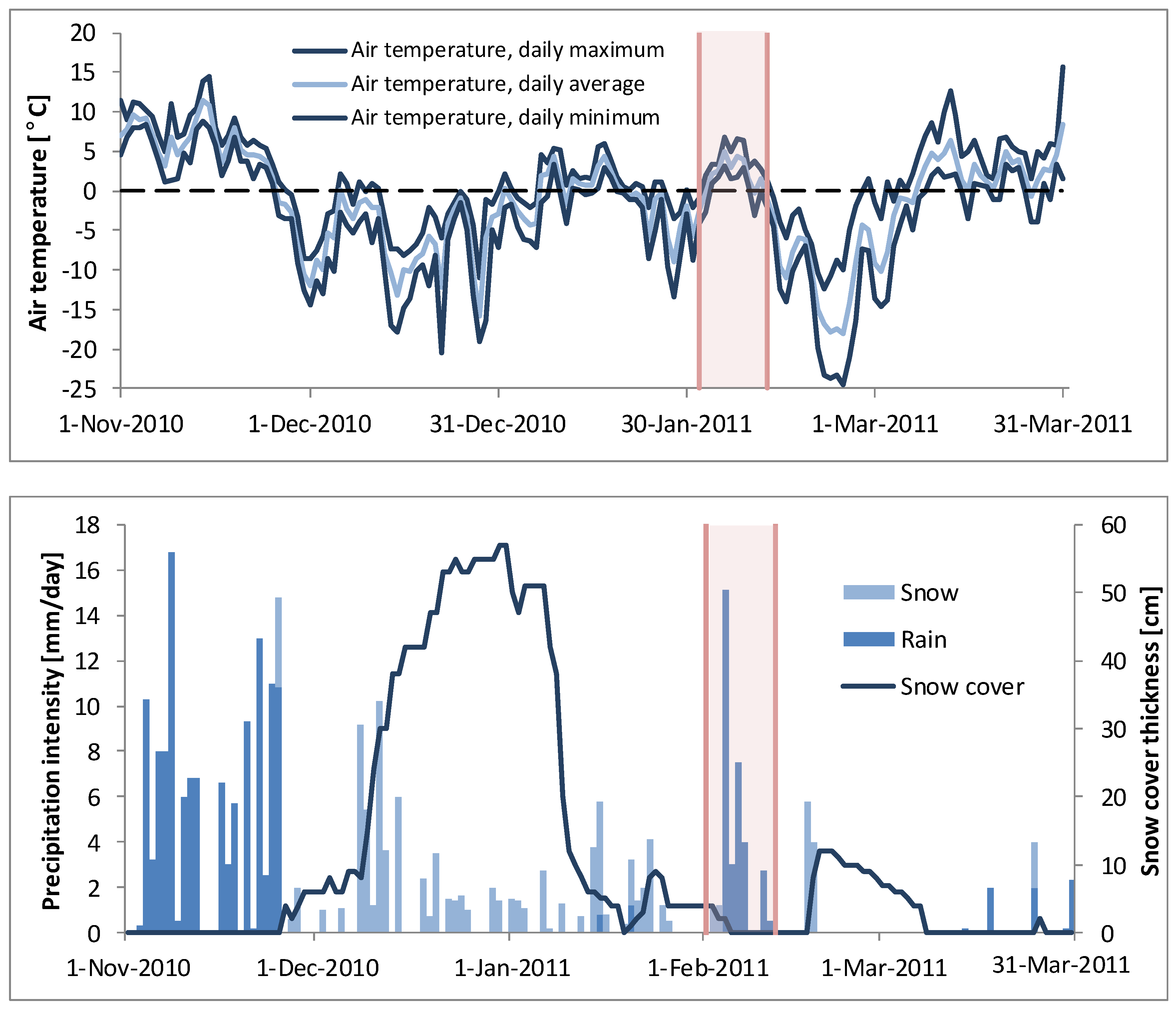
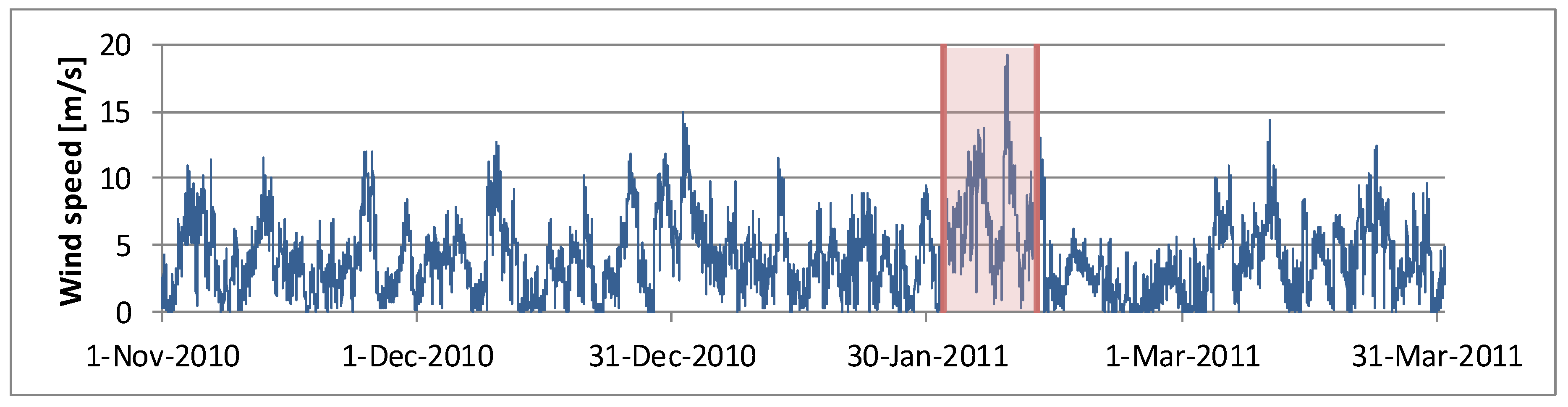
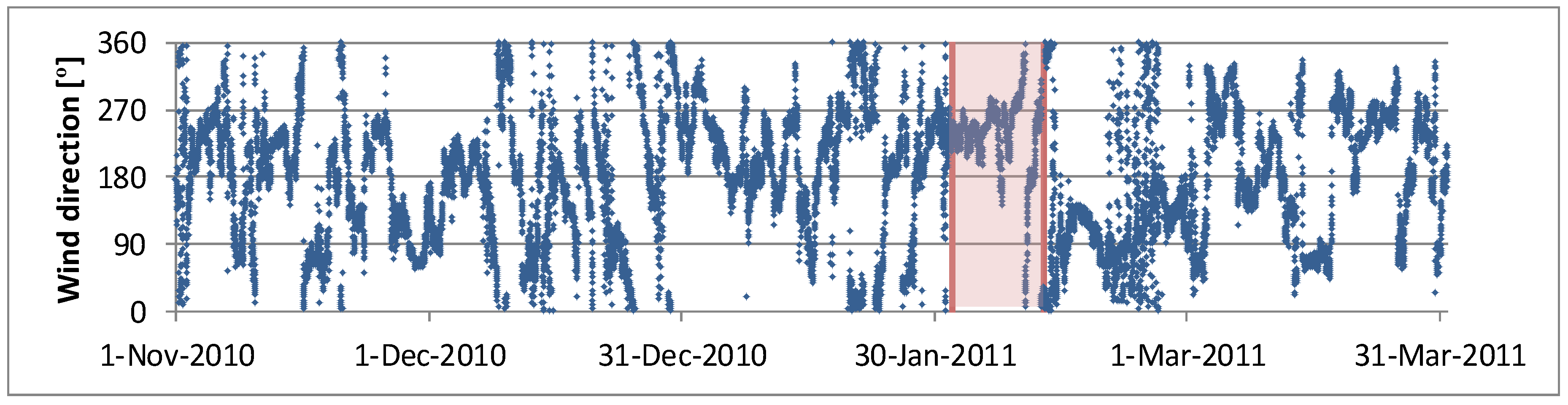
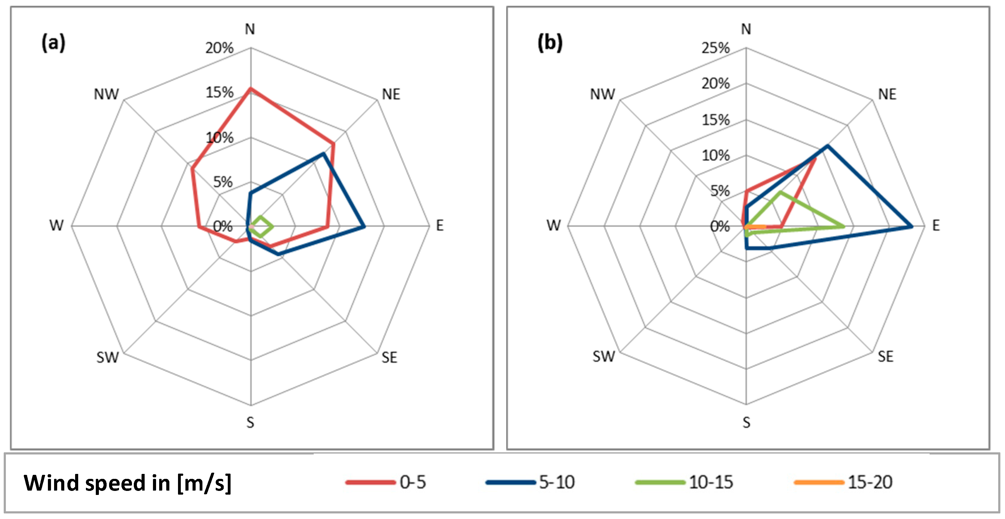
The calibration of the bed and ice roughness was preceded by using hydrodynamic and meteorological conditions as observed during the winter season 2010/2011. That winter, the lowest air temperature recorded in the Polish part of the Vistula Lagoon area reached −24.6 °C and took place on 24 February 2011. The winter season 2010/2011 was characterized by severe frosts that started early, in the second half of November 2010, and lasted until mid-January 2011. As a result of such low and long-lasting air temperatures, the ice cover developed over the entire extent of the lagoon. During this first cold wave, unusual and abnormal snowfalls triggered snow cover reaching up to 60 cm (see Figure 4). Next, starting from 9 January, the air temperature increased above zero, causing most of the snow cover to melt, affecting an increased river flow observed over the next days. After a short period of thaw, the weather was cooler again for 10 days. Starting from 1 February, anticyclone circulations with strong winds and rainfall caused the breakup and drifting of the ice on the lagoon. Because the wind was mainly blowing from the north east and east direction, see Figure 6b, ice was blown towards the southern shore of the lagoon and extensive hammocks were formed [39]. Ice movement was caused by the wind and also by the water inflow to the lagoon from the Baltic Sea due to the high storm surge. The wind speed and direction recorded during the entire season is presented in Figure 5. Table 1 summarizes wind distribution over the entire season as shown on the wind rose in Figure 6a. The wind data were measured with 10 min intervals by the Institute of Meteorology and Water Resources in Frombork (location shown in Figure 1). All data used in the study and presented in the paper are public and can be found on https://dane.imgw.pl/.
Water surface elevation measured in the Hel peninsula was used as the sea side boundary condition for the calibration of the model. From the land side, for all the inflowing rivers to the lagoon, water discharge boundary conditions were set. Historical data of the water discharge exist only on the Elbląg and Pasłęka rivers, thus historical hydrographs were used for calibrations. For the Nogat and the Pregolya, the average discharge was used [18], which is a simplification, but the contribution of the rivers to the ice dynamics on the Vistula Lagoon is negligible, and limited to the areas in the direct vicinity of the river estuaries.
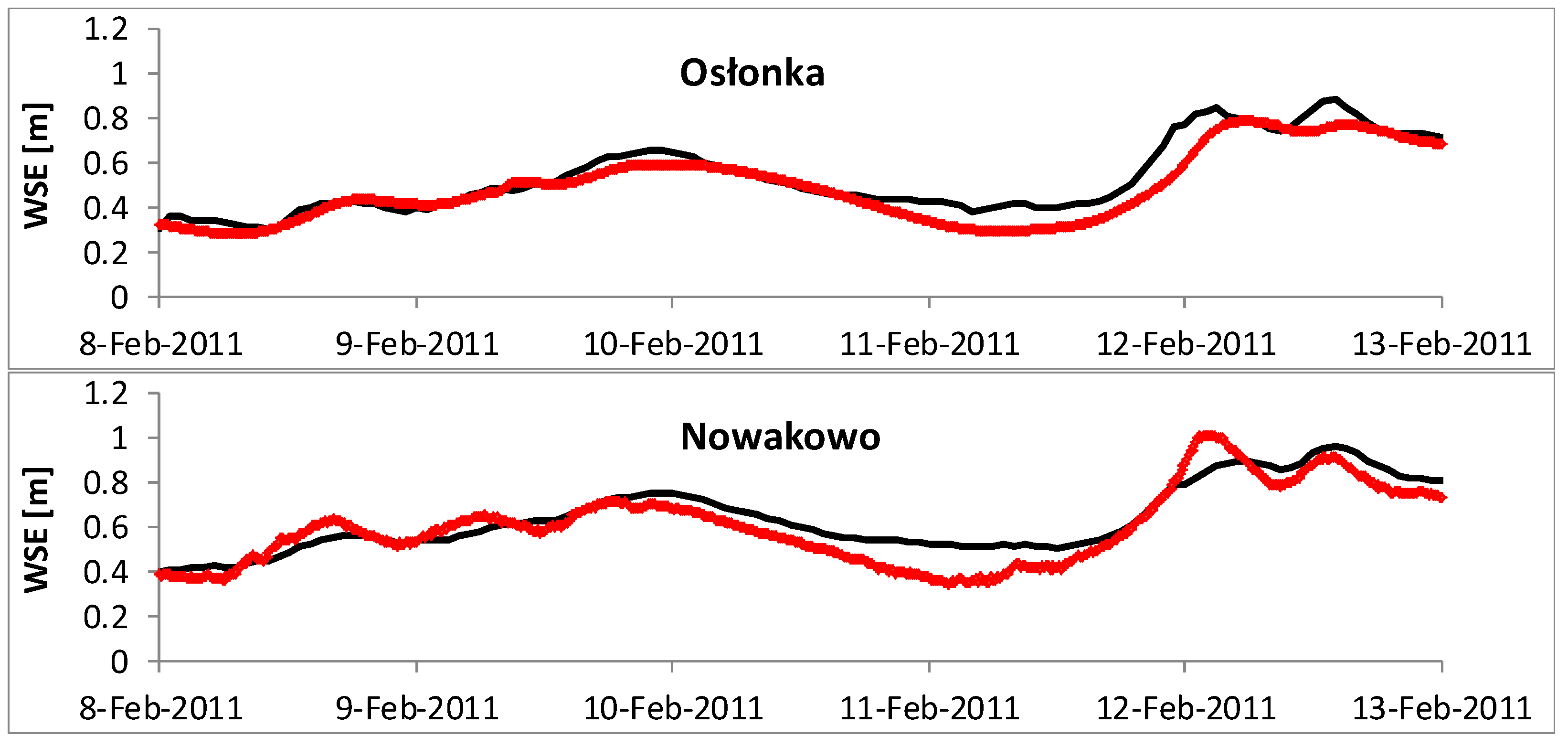
Model calibration was done to compare water surface elevations at four locations along the Polish shore of the lagoon: namely Osłonka, Nowakowo, Toklmicko, and Nowa Pasłęka (see the locations in Figure 1). It was assumed that the ice covers the entire lagoon and its initial thickness was 0.2 m. The initial ice thickness was calculated with the freezing degree day method (FDD) by using the daily average air temperature for the entire season as shown on Figure 4. Ice monitoring in the Vistula Lagoon is rather scattered and there are no systematic ice thickness measurements for the winter season 2010–2011. However, Girjatowicz [6] measured an ice thickness of 21 cm on 8 February 2011 near Frombork, which is consistent with the calculated value. In the model simulation, ice cover of 20 cm initially covered the entire lagoon and at the beginning of the calibration period all ice was assumed to break up and was able to move according to the wind and water flow drag forces. The bed roughness and ice roughness were calibrated by a series of simulation runs. The final results of the calibration are shown in Figure 7, where the red dots represent the observed WSE and the black line is the simulated water level at each of the locations. It is worth noting that the water level increase starting on 12 February was mainly affected by high wind (nearly 20 m/s) but also increased fresh water inflow due to snow melting (see Figure 4). In addition to graphically presented results, the root-mean-square deviation (RMSD) was calculated according to the formula:
RMSD results for all stations are shown in a Table 2. The objective of limiting inconsistencies between the observed and simulated values was satisfactorily met and the model parameters were next used for a case scenario analysis.
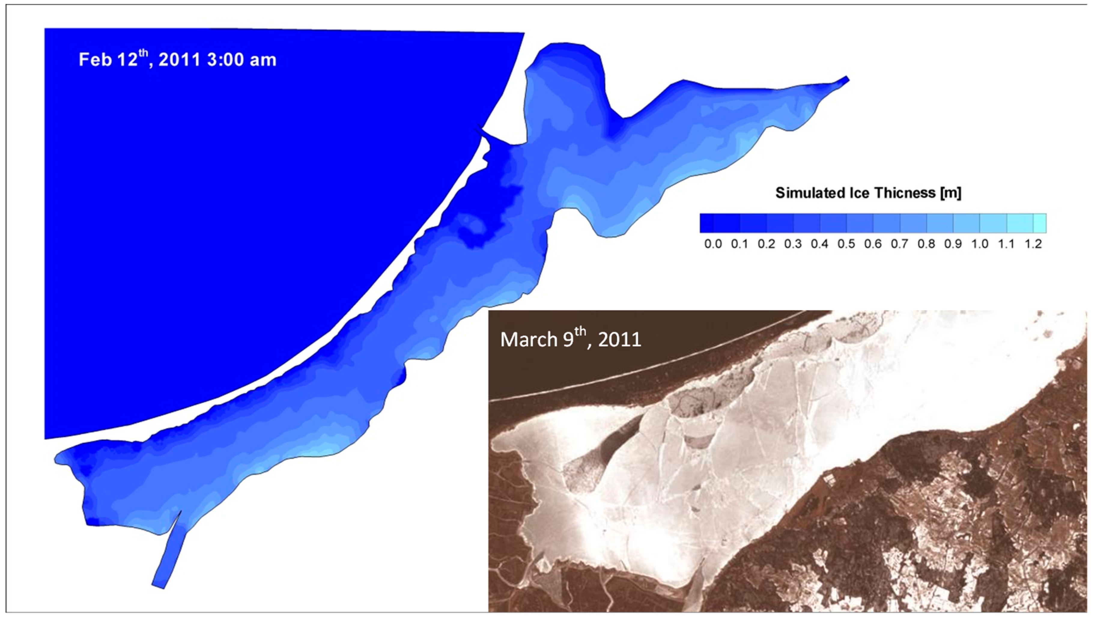
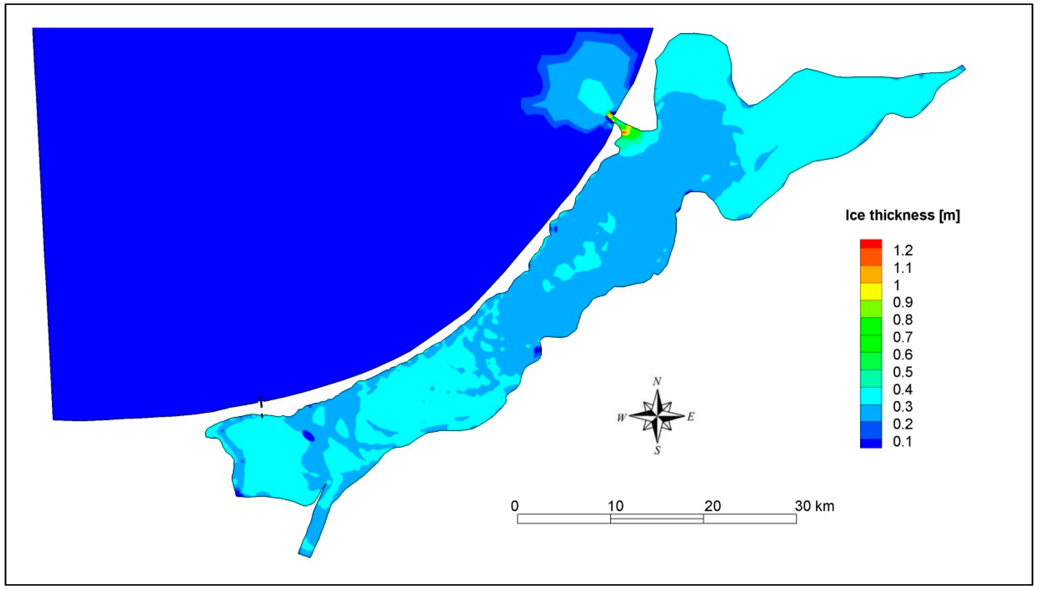
In addition to the WSE calibration, the length and the thickness of ice thrusting on the lagoon shore were analyzed and compared with forms observed in the field. According to [6], the longest ice thrust observed in 2011 on the Vistula Lagoon was 140 m and the thickness of the ice at the shore was up to five times the initial thickness of the ice cover. The simulation results show ice piled up on the shore between Frombork and Tolkmicko and the largest thickness was up to 1.1 m and occurred on the night of 11–12 February, which is consistent with the observations. Satellite images from 9 March 2011 (Landsat 5) showed fractured cover and residual portions of ice hummocks, as seen in Figure 8.
3.2. Sensitivity Analysis of Ice Conditions in the Vistula Lagoon
In the study, numerical simulations were performed for various flow and wind conditions which cover the most severe conditions for the Vistula Lagoon. The sensitivity analysis was made by varying the model parameters, which are wind speed, wind direction, and water level, in the Gulf of Gdańsk. All simulation cases run for the model domain included the proposed bathymetry and new strait. However, to make the simulations more reasonable, the new lock in Nowy Świat was constantly closed to avoid any water flow through the proposed strait. According to the project, the lock will only be open for navigation purposes, thus the flow exchange will be limited to the amount filled in the lock chamber. A comparison of the maximum ice loads predicted by DynaRICE showed that high wind velocity yielded the highest ice supply from the northern part of the lagoon and produced the most severe ice conditions in the Nowy Świat–Elbląg area. The water level in the southern Baltic Sea also affects the ice dynamics, leading to ice loads on lock harbors inside the lagoon.
The results of the DynaRICE simulations for four hypothetical cases are presented in the following section. The first two cases represent typical storm events with winds blowing along the lagoon, from NE and from SW. In each case, the wind speed was specified as 12 m/s with a duration of 24 h. The water level at the sea is 0 m a.s.l., the initial ice thickness is 0.2 m and the discharge from the Nogat, Elbląg, Pasłęka, and Pregolya rivers is equal to the long-term average flow. In all scenarios, the breakup ice condition was simulated. The DynaRICE model simulates ice dynamics by using the SPH method which is a pure Lagrangian approach. In this method, a continuum is simulated by sufficient number of elements which are referred to particles. In the used method, the mass density of any point in the space is obtained by summing up the contributions from all particles surrounding that point. However, to simulate ice cover, ice particles are kept in initial locations up to the moment defined as the initiation of the ice cover breakup. It could be a function of the water surface elevation change, but also can be arbitrarily introduced at the time of the breakup. In all the simulations of the sensitivity study, since the ice properties were not known, it was assumed that the breakup occurred at the beginning of the simulation time.
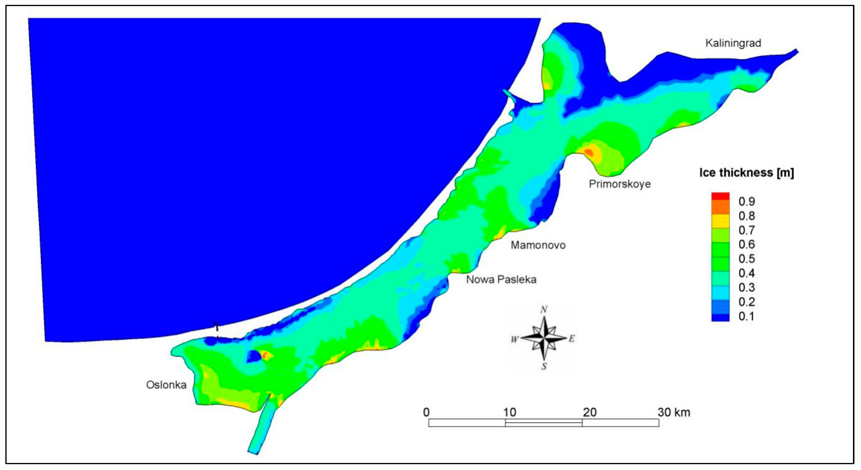
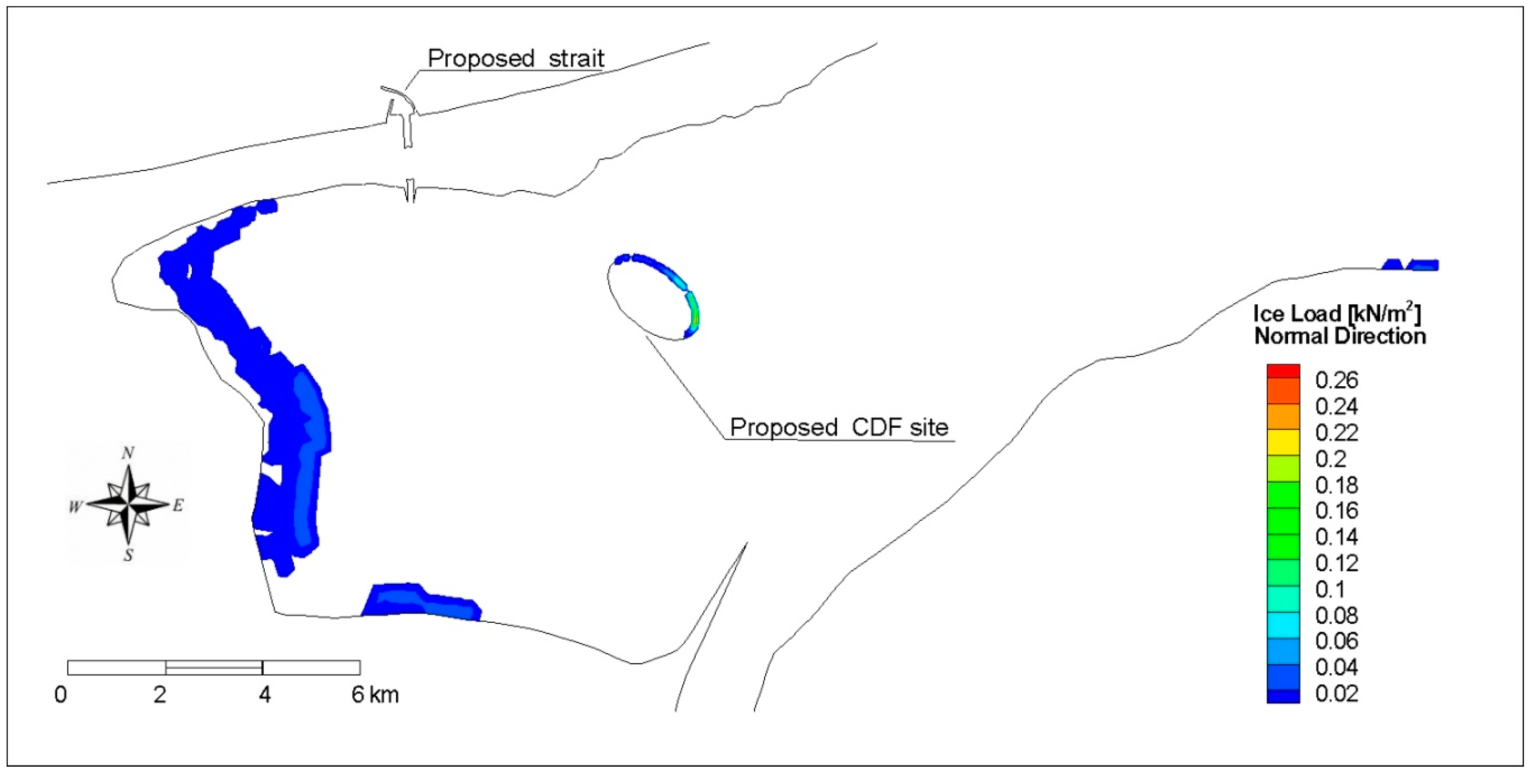
The results show that wind blowing from the NE causes the drift of all ice in the lagoon in a SW direction and an accumulation along the shore, as seen in Figure 9. Three main jam sites are formed, from which the first has its toe near Primorkoye and is formed from the ice dragged from the Kaliningrad shores and Primorskaya bay. The next jam site is a consequence of the narrowing of the lagoon near the Mamonowo–Nowa Pasłęka area (Polish–Russian border). Once the ice passes the narrow area, it moves down to the Polish part of the lagoon and finally forms the last jam on the eastern side of the artificial island and near Osłonka. The last jam location is of principle interest because the proposed CDF site is planned to be transformed into a habitat improvement project (HIP), and thus it needs to withstand the force caused by the ice. The results obtained from the mathematical model show a 0.8-thick ice hummock formed at the island after 24 h of simulation. This formation caused an ice load on the entire eastern shore of the island varying from 20 to nearly 260 N/m2 as seen in Figure 10. Since the NE wind drags ice from the Vistula Spit, there is no load on the harbor of the new strait.
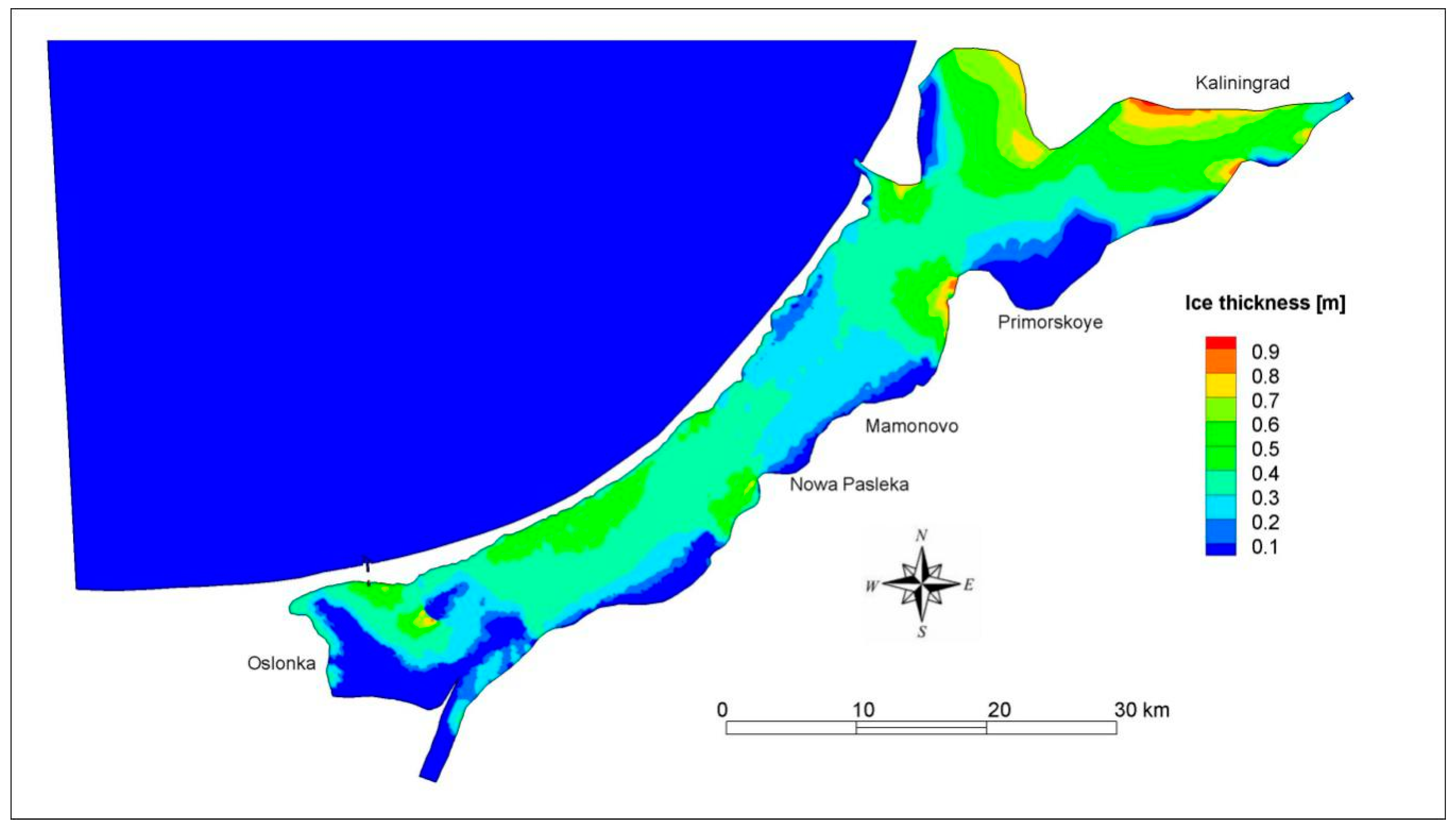
The case with the opposite wind direction (blowing from a SW direction) is less critical for the proposed CDF site. Ice is pushed towards the eastern and northern side of the lagoon and some accumulation is formed near Primorskoye and along the dams boarded the Kaliningrad Sea Canal from the lagoon side, as seen in Figure 11. There is also a small ice hummock on the western shore of the island; however, due to the small ice field, the force built up at the CDF shore is relatively small.
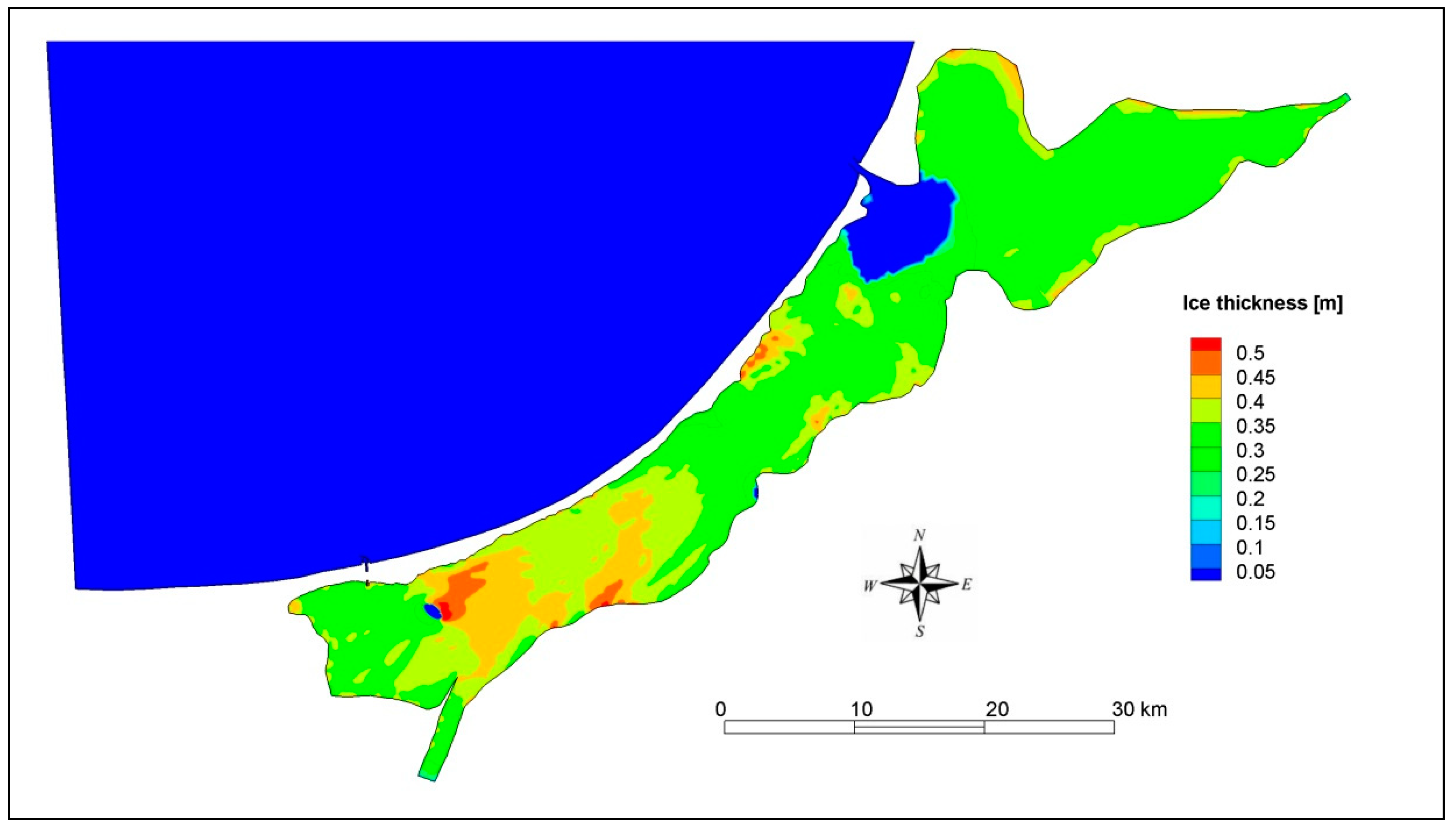
The next scenarios are high and low sea level conditions at +1 m a.s.l. and −1 a.s.l. In these cases, to avoid a multiplication of the effect, the wind was specified as 0 m/s, and the ice conditions were identical to previous cases. Both cases caused intense water dynamics within the lagoon, resulting from flow exchange in the Baltijsk strait. High water levels at the sea is a typical storm condition for the southern Baltic Sea; however, the water surface elevation rarely increases by 1 m above the normal level in the Bay of Gdańsk [40]. The described scenario is an artificial case referring to a 100-year storm condition, as determined for the Port of Gdańsk by the Institute of Meteorology and Water Resources. Resulting from the high surge, a large amount of sea water inflow entered the lagoon and ice cover was pushed from the direct vicinity of the Strait of Baltijsk. After 24 h of steady high water level at the sea side boundary, significant displacement of the ice inside the lagoon was observed. Ice was dragged to the lagoon shores, and thrusting occurred nearly along the entire shore. The largest accumulation is affected by the construction of the artificial island, which stopped a large amount of ice which jammed against the eastern bank of the island. The accumulation reached up to 0.5 m thick (2.5 initial ice thickness) with a length of the jam up to 20 km, as seen in Figure 12. This ice thrust into the island causing a large force of up to 100 N/m2 observed on the south-eastern shore. It is noteworthy that the scenario did not include the wind effect, which may multiply the load.
The case with a low sea level resulted in emptying the lagoon, and ice was pushed toward the Strait of Baltijsk. Due to the limited clearance of the strait and large ice parcels in the lagoon, an ice jam formed at the lagoon side of the strait. As a consequence, only a little amount of the ice moved out into the Baltic Sea, and after 24 h of simulation, less than 2% of all ice drifted down the strait to the sea. On the entire lagoon, the ice was fractured and was dragged slowly toward the strait; however, no other significant accumulation occurred, as seen in Figure 13. A limited pile was formed on the western shore of the artificial island and this accumulation was dragged by the moving water and produced a load of up to 20 N/m2. As before, in this simulation, the wind effect was omitted; therefore, the effect could be expected to increase in natural conditions.
4. Conclusions
The results of the two-dimensional numerical simulations of the ice dynamics of the Vistula Lagoon induced by storms and strong winds allow the following to be concluded:
- even though the Vistula Lagoon freezes nearly every year, the ice dynamics of the lagoon are limited only to the breakup periods and are often driven by strong winds and storm surges
- for the calibration period, the comparison of calculated and observed water levels in the lagoon shows that the proposed mathematical model and its numerical solution ensure satisfactory accuracy of the results
- ice hummocks simulated for the calibration period occurred at locations indicated in the literature, and their thickness was similar to that observed
- the long-lasting NE winds can result in ice movement towards the western and southern parts of the lagoon and a jam will be formed at the shore of the proposed CDF site, which is being considered to be a HIP in the future
- according to the simulation results, the proposed armoring of the CDF site will need to withstand a force of up to 260 N/m, which is caused by the ice load produced by ice thrusting,
- in the case of a low water level at the Baltic sea, ice was moved towards the Strait of Baltijsk, and due to its limited width, ice may cause accumulation at the lagoon side of the strait, which should be relieved by icebreakers.
Author Contributions
Conceptualization, methodology, software, validation T.K.; formal analysis, investigation T.K., M.S. and P.Z.; data curation T.K.; writing—original draft preparation T.K.; writing—review and editing T.K. and M.S.; visualization T.K.
Funding
This research received no external funding.
Conflicts of Interest
The authors declare no conflict of interest.
References
- Kjerfve, B. Coastal Lagoons. In Elsevier Oceanography Series; Kjerfve, B., Ed.; Coastal Lagoon Processes; Elsevier: Amsterdam, The Netherlands, 1994; Volume 60, pp. 1–8. [Google Scholar]
- Chubarenko, B.; Margoński, P. The Vistula Lagoon. In Ecology of Baltic Coastal Waters; Schiewer, U., Ed.; Ecological Studies; Springer: Berlin/Heidelberg, Germany, 2008; pp. 167–195. ISBN 978-3-540-73524-3. [Google Scholar]
- Kruk, M.; Kempa, M.; Tjomsland, T.; Durand, D. The use of mathematical models to predict changes in the environment of the Vistula Lagoon. In Vistula Lagoon—Natural Environment and Modern Methods of His Research Project on the Example of Visla; Publishing PWSZ: Elbląg, Poland, 2011; pp. 165–180. [Google Scholar]
- Nadolny, A.; Samulak, M. Construction of a Waterway Connecting the Vistula Lagoon with the Bay of Gdańsk; Maritime Office: Gdynia, Poland, 2017; pp. 1–14.
- Shen, H.T. Mathematical modeling of river ice processes. Cold Reg. Sci. Technol. 2010, 62, 3–13. [Google Scholar] [CrossRef]
- Girjatowicz, J.P. Ice thrusting and hummocking on the shores of the Southern Baltic Sea’s coastal lagoons. J. Coast. Res. 2014, 30, 456–464. [Google Scholar]
- Girjatowicz, J.P. Ice Cover Atlas for Polish Baltic Coastal Waters, 2nd ed.; ZUT, Maritime Office: Szczecin, Poland, 1990. [Google Scholar]
- Girjatowicz, J.P. Ice condition in the Vistula Lagoon. Pol. Geogr. Rev. 1994, 66, 119–132. [Google Scholar]
- Herman, A. Ice cover of the Vistula Lagoon. In Vistula Lagoon; Wydawnictwo Naukowe PWN: Warszawa, Poland, 2018; ISBN 978-83-01-19974-6. [Google Scholar]
- Chubarenko, B.; Chechko, V.; Kileso, A.; Krek, E.; Topchaya, V. Hydrological and sedimentation conditions in a non-tidal lagoon during ice coverage—The example of Vistula Lagoon in the Baltic Sea. Estuar. Coast. Shelf Sci. 2019, 216, 38–53. [Google Scholar] [CrossRef]
- Zhelezova, E.; Krek, E.; Chubarenko, B. Characteristics of the polynya in the Vistula Lagoon of the Baltic Sea by remote sensing data. Int. J. Remote Sens. 2018, 39, 9453–9464. [Google Scholar] [CrossRef]
- Jevrejeva, S.; Drabkin, V.V.; Kostjukov, J.; Lebedev, A.A.; Leppäranta, M.; Mironov, Y.U.; Schmelzer, N.; Sztobryn, M. Baltic Sea ice seasons in the twentieth century. Clim. Res. 2004, 25, 217–227. [Google Scholar] [CrossRef] [Green Version]
- Liu, L.; Li, H.; Shen, H.T. A two-dimensional comprehensive river ice model. In Proceedings of the 18th IAHR Symposium on River Ice, Sapporo, Japan, 28 August–1 September 2006. [Google Scholar]
- Szymkiewicz, R. A mathematical model of storm surge in the Vistula Lagoon, Poland. Coast. Eng. 1992, 16, 181–203. [Google Scholar] [CrossRef]
- Catewicz, Z.; Jankowski, A. Model H-N of stationary flows in Vistula Lagoon. Podstawy Gospodarki w Środowisku Morskim III. Studia i Materiały Oceanologiczne 1983, 40, 223–249. [Google Scholar]
- Szydlowski, M.; Kolerski, T.; Zima, P. Impact of the artificial strait in the vistula spit on the hydrodynamics of the Vistula Lagoon (Baltic Sea). Water 2019, 11, 990. [Google Scholar] [CrossRef]
- Chubarenko, B.V.; Chubarenko, I.P. Regionalization of river Pregel estuary and Russian part of Vistula Lagoon on hydrophysical parameters. In Proceedings of the International Conference on Regionalization in Hydrology, Braunschweig, Germany, 10–14 March 1997; pp. 41–44. [Google Scholar]
- Kwiatkowski, J.; Rasmussen, E.K.; Ezhova, E.; Chubarenko, B. The eutrophication model of the Vistula Lagoon. Oceanol. Stud. 1997, 26, 5–33. [Google Scholar]
- Chubarenko, I.; Tchepikova, I. Modelling of man-made contribution to salinity increase into the Vistula Lagoon (Baltic Sea). Ecol. Model. 2001, 138, 87–100. [Google Scholar] [CrossRef]
- Chubarenko, B.V.; Leitsina, L.V.; Esiukova, E.E.; Kurennoy, D.N. Model analysis of the currents and wind waves in the Vistula Lagoon of the Baltic Sea. Oceanology 2012, 52, 748–753. [Google Scholar] [CrossRef]
- Bielecka, M.; Kazmierski, J. A 3D mathematical model of Vistula Lagoon hydrodynamics-general assumptions and results of preliminary calculations. Ground Water 2003, 80, 2–4. [Google Scholar]
- Shen, H.T.; Liu, L. Shokotsu River ice jam formation. Cold Reg. Sci. Technol. 2003, 37, 35–49. [Google Scholar] [CrossRef]
- Shen, H.T. River Ice Processes. In Advances in Water Resources Management; Handbook of Environmental Engineering; Springer: Cham, Poland, 2016; pp. 483–530. ISBN 978-3-319-22923-2. [Google Scholar]
- Knack, I.M.; Shen, H.T. A numerical model study on Saint John River ice breakup. Can. J. Civ. Eng. 2016, 45, 817–826. [Google Scholar] [CrossRef]
- Shen, H.T.; Gao, L.; Kolerski, T.; Liu, L. Dynamics of Ice Jam Formation and Release. J. Coast. Res. 2008, 52, 25–32. [Google Scholar] [CrossRef]
- Kolerski, T.; Shen, H.T. Possible effects of the 1984 St. Clair River ice jam on bed changes. Can. J. Civ. Eng. 2015, 42, 696–703. [Google Scholar] [CrossRef]
- Knack, I.M.; Shen, H.T. Numerical modeling of ice transport in channels with river restoration structures. Can. J. Civ. Eng. 2017, 44, 813–819. [Google Scholar] [CrossRef]
- Shen, H.T.; Lu, S.; Crissman, R.D. Numerical simulation of ice transport over the Lake Erie-Niagara River ice boom. Cold Reg. Sci. Technol. 1997, 26, 17–33. [Google Scholar] [CrossRef]
- Liu, L.; Shen, H.T. Numerical Simulation of River Ice Control with Booms; Engineer Research and Developemnt Center, Cold Regions Research and Engineering Laboratory: Hanover, NH, USA, 2000; p. 38. [Google Scholar]
- Szydlowski, M.; Kolerski, T. Numerical Modeling of Water and Ice Dynamics for Analysis of Flow Around the Kiezmark Bridge Piers. In Free Surface Flows and Transport Processes; Springer: Cham, Poland, 2018; pp. 465–476. [Google Scholar]
- Kolerski, T.; Shen, H.T.; Knack, I.M. A nested model for river Ice dynamics. In Proceedings of the 20th IAHR Ice Symposium, Lahti, Finland, 14–18 June 2010. [Google Scholar]
- Kolerski, T.; Shen, H.T. Ice Modeling for HIP in the Upper Niagara River. In Progress Report submitted to Gomez and Sullivan Engineers, PC; Clarkson University: Potsdam, NY, USA, 2008. [Google Scholar]
- Kolerski, T.; Shen, H.T.; Kioka, S. A numerical model study on ice boom in a coastal lake. J. Coast. Res. 2013, 291, 177–186. [Google Scholar] [CrossRef]
- Shen, H.T.; Su, J.; Liu, L. SPH simulation of river ice dynamics. J. Comput. Phys. 2000, 165, 752–770. [Google Scholar] [CrossRef]
- Ji, S.; Shen, H.T.; Wang, Z.; Shen, H.H.; Yue, Q. A viscoelastic-plastic constitutive model with Mohr-Coulomb yielding criterion for sea ice dynamics. Acta Oceanol. Sin. 2005, 24, 54. [Google Scholar]
- Wu, J. Prediction of near-surface drift currents from wind velocity. J. Hydraul. Div. 1973, 99, 1291–1302. [Google Scholar]
- Liu, L.; Shen, H.T. A Two-Dimensional Characteristic Upwind Finite Element Method for Transitional Open Channel Flow; Clarkson University: Potsdam, NY, USA, 2003; p. 54. [Google Scholar]
- Kolerski, T. Mathematical modeling of ice dynamics as a decision support tool in river engineering. Water 2018, 10, 1241. [Google Scholar] [CrossRef]
- Girjatowicz, J.P. Forms of onshore ice thrusting in coastal lagoons of the southern Baltic Sea. J. Cold Reg. Eng. 2014, 29, 04014008. [Google Scholar] [CrossRef]
- Szymkiewicz, R. Hydrodynamics of Vistula Lagoon; Polish Academy of Sciences: Warsaw, Poland, 1992. [Google Scholar]
Figure 1.
Location of the Vistula Lagoon; blue triangles indicate water surface elevation (WSE) boundary stations in the lagoon; the red triangle indicates the meteorological station in Frombork.
Figure 1.
Location of the Vistula Lagoon; blue triangles indicate water surface elevation (WSE) boundary stations in the lagoon; the red triangle indicates the meteorological station in Frombork.

Figure 2.
Project of the confined disposal facility (CDF) in the Vistula Lagoon; plane view (a) and cross-sectional view (b) [4].
Figure 2.
Project of the confined disposal facility (CDF) in the Vistula Lagoon; plane view (a) and cross-sectional view (b) [4].

Figure 3.
Bathymetry of the Vistula Lagoon and the southern Baltic Sea with the finite element mesh used in the model; the red oval indicates the artificial island; the thick blue line represents WSE boundary conditions; red arrows represent water discharge boundary conditions.
Figure 3.
Bathymetry of the Vistula Lagoon and the southern Baltic Sea with the finite element mesh used in the model; the red oval indicates the artificial island; the thick blue line represents WSE boundary conditions; red arrows represent water discharge boundary conditions.

Figure 4.
Air Temperature, precipitation and snow cover thickness measured at Frombork meteorological station in the winter season 2010/2011; the pink rectangle indicates the calibration period (1 February–12 February); data from https://dane.imgw.pl/.
Figure 4.
Air Temperature, precipitation and snow cover thickness measured at Frombork meteorological station in the winter season 2010/2011; the pink rectangle indicates the calibration period (1 February–12 February); data from https://dane.imgw.pl/.

Figure 5.
Wind speed and direction measured at Frombork in the winter season 2010/2011; the pink rectangle indicates the calibration period (1 February–12 February); data from https://dane.imgw.pl/.
Figure 5.
Wind speed and direction measured at Frombork in the winter season 2010/2011; the pink rectangle indicates the calibration period (1 February–12 February); data from https://dane.imgw.pl/.


Figure 6.
Wind rose for the winter season 2010/2011 (a) and for the calibration period 1–12 February (b); data from https://dane.imgw.pl/.
Figure 6.
Wind rose for the winter season 2010/2011 (a) and for the calibration period 1–12 February (b); data from https://dane.imgw.pl/.

Figure 7.
Measured (red dots) and simulated (black line) WSE in February 2011, at locations along the South Polish shore of the Vistula Lagoon.
Figure 7.
Measured (red dots) and simulated (black line) WSE in February 2011, at locations along the South Polish shore of the Vistula Lagoon.


Figure 8.
Simulated ice thickness on 12 February 2011 and a satellite image of the southern part of the Vistula Lagoon (Landsat 5, 9 March 2011; https://eos.com/landviewer/).
Figure 8.
Simulated ice thickness on 12 February 2011 and a satellite image of the southern part of the Vistula Lagoon (Landsat 5, 9 March 2011; https://eos.com/landviewer/).

Figure 9.
Simulation results of ice thickness for wind blowing from a North-East direction.

Figure 10.
Simulation results of ice load on the shore of the Vistula Lagoon for the case with wind blowing from a North-East direction.
Figure 10.
Simulation results of ice load on the shore of the Vistula Lagoon for the case with wind blowing from a North-East direction.

Figure 11.
Simulation results of the ice thickness for a wind blowing from a South-West direction.

Figure 12.
Simulation results of ice thickness for a high water level at the Baltic Sea.

Figure 13.
Simulation results of ice thickness for a low water level at the Baltic Sea.


Table 1.
Distribution of wind directions in percent during the winter season 2010/2011 recorded in Frombork with respect to four speed ranges; data from https://dane.imgw.pl/.
Table 1.
Distribution of wind directions in percent during the winter season 2010/2011 recorded in Frombork with respect to four speed ranges; data from https://dane.imgw.pl/.
| Wind Speed (m/s) | Wind Directions (%) | ||||||||
|---|---|---|---|---|---|---|---|---|---|
| N | NE | E | SE | S | SW | W | NW | Σ | |
| 0–5 | 15.40% | 13.10% | 8.61% | 3.18% | 1.34% | 2.30% | 5.74% | 9.19% | 58.86% |
| 5–10 | 3.79% | 11.54% | 12.69% | 4.32% | 1.55% | 0.50% | 0.21% | 0.46% | 35.05% |
| 10–15 | 0.00% | 1.49% | 2.37% | 1.58% | 0.37% | 0.00% | 0.00% | 0.00% | 5.82% |
| 15–20 | 0.00% | 0.01% | 0.25% | 0.00% | 0.00% | 0.02% | 0.00% | 0.00% | 0.27% |
| 0–20 | 19% | 26% | 24% | 9% | 3% | 3% | 6% | 10% | 100% |
Table 2.
Calculated root-mean-square deviation (RMSD) for the calibration period from 6 February to 13 February 2011.
Table 2.
Calculated root-mean-square deviation (RMSD) for the calibration period from 6 February to 13 February 2011.
| Station | Osłonka | Nowakowo | Tolkmicko | Nowa Pasłęka |
|---|---|---|---|---|
| RMSD (m) | 0.065 | 0.076 | 0.065 | 0.086 |
© 2019 by the authors. Licensee MDPI, Basel, Switzerland. This article is an open access article distributed under the terms and conditions of the Creative Commons Attribution (CC BY) license (http://creativecommons.org/licenses/by/4.0/).
Share and Cite
MDPI and ACS Style
Kolerski, T.; Zima, P.; Szydłowski, M. Mathematical Modeling of Ice Thrusting on the Shore of the Vistula Lagoon (Baltic Sea) and the Proposed Artificial Island. Water 2019, 11, 2297. https://doi.org/10.3390/w11112297
AMA Style
Kolerski T, Zima P, Szydłowski M. Mathematical Modeling of Ice Thrusting on the Shore of the Vistula Lagoon (Baltic Sea) and the Proposed Artificial Island. Water. 2019; 11(11):2297. https://doi.org/10.3390/w11112297
Chicago/Turabian StyleKolerski, Tomasz, Piotr Zima, and Michał Szydłowski. 2019. "Mathematical Modeling of Ice Thrusting on the Shore of the Vistula Lagoon (Baltic Sea) and the Proposed Artificial Island" Water 11, no. 11: 2297. https://doi.org/10.3390/w11112297
Note that from the first issue of 2016, this journal uses article numbers instead of page numbers. See further details here.