Treatment of Trichloroethylene with Photocatalyst-Coated Optical Fiber

1
Department of Environmental Science and Engineering, National Pingtung University of Science and Technology, No. 1, Shuehfu Rd., Neipu, Pingtung 91201, Taiwan
2
Department of Environmental Engineering and Science, Feng Chia University, No. 100, Wenhwa Rd., Seatwen, Taichung 40724, Taiwan
3
Emerging Compounds Research Center (ECOREC), National Pingtung University of Science and Technology, No. 1, Shuehfu Rd., Neipu, Pingtung 91201, Taiwan
*
Author to whom correspondence should be addressed.
Water 2019, 11(11), 2391; https://doi.org/10.3390/w11112391
Submission received: 30 August 2019
/
Revised: 31 October 2019
/
Accepted: 4 November 2019
/
Published: 14 November 2019
(This article belongs to the Special Issue Desalination and Wastewater Treatment: Chemical, Physical, and Biological Methods)
Abstract
:In this present study, we investigated the effect of photocatalyzation on the degradation of trichloroethylene (TCE) in the aqueous phase by a photocatalyst-coated plastic optical fiber (POF). Two light-emitting diodes (LEDs) with low light intensity were used as the light source and TiO2 and ZnO were used as photocatalysts, which were characterized by scanning electron microscope (SEM) and UV-Vis diffuse reflectance spectroscopy (DRS). The para-chlorobenzoic acid (pCBA) was used as the hydroxyl radical probe for kinetic study and for the calculation of hydroxyl radical conversion rate (ROH,UV ). Experimental results show that POF coated with TiO2 exhibited higher degradation efficiency of TCE in basic solution, but POF coated with ZnO performed better in acidic solution. The increase of coating times resulted in the decrease in degradation efficiency of TCE due to increased thickness of the photocatalyst layer. The enhancement of light intensity contributed to the improvement of photocatalytic treatment efficiency. The ROH,UV for TiO2 and ZnO coated POF increased from 2 × 10³ to 8 × 10³ M s cm2 mJ−1 and from 8 × 10² to 2 × 10³ M s cm2 mJ−1, respectively, as the pH increased from 4 to 10.
1. Introduction
In recent years, the issue of groundwater pollution has received much attention. The treatment techniques for soil and groundwater pollution can be classified into three types: in situ, on-site, and off-site [1]. The current groundwater treatment mainly focuses on local and off-site treatment. For the local treatment, it is difficult to determine the optimal dosage of applied chemicals. The efficacy of the treatment always depends on the dosage used. Probably, the highest chemical dosage may result in some adverse effects on the environment. Off-site treatment is mainly used to treat contaminated groundwater in a wastewater treatment system. On the other hand, the professional wastewater treatment technology is an effective method that can be used to remove organic pollutants from water; but it is more expensive than local treatment and cannot be used widely. Thus, this study intends to develop a facile treatment technology, with the addition of negligible/absence of chemical reagents, that can effectively remove organic pollutants from the groundwater. Furthermore, the reliability, feasibility and cost are the main concerns in order to avoid the drawbacks of some other conventional treatment methods in practice nowadays.
The photocatalytic technology utilizes the energy of light to transfer electrons between the valence band and the conduction band of the catalyst, thereby producing conduction-band electrons and valence-band holes. The photocatalytic activity produces highly oxidative hydroxyl radicals (•OH) from water, which can effectively mineralize or decompose chemical substances in the water. In recent years, to benefit from the photocatalyst preparation technology, substantial development has been needed to enhance the photocatalytic technology in order to deal with pollutants. At present, the commonly used coating techniques include impregnation, dip-coating and sputtering. Photocatalysts are coated on a solid carrier, which eliminates the demand, compared with in suspension, for the additional filtration process. In addition, fiber optic technology has been used globally in telecommunications engineering for information transmission. Previous reports on optical photocatalysis mainly focused on the gas phase [2,3,4,5], but recent studies have proven to be effective in aqueous phase treatment [6,7]. Ma et al. used titanium dioxide (TiO2) photocatalyst-coated optical fiber reactors at different UV light intensities of the initial concentration of acetone, to investigate the effect of treatment of acetone in the air [3]. The experimental results show that increasing the UV light intensity or decreasing the initial acetone concentration enhances the mineralization of acetone, while the optical reactor’s apparent quantum yield is two to three times that of a conventional photoreactor. This is due to the optical fiber’s optical properties, which allow it to transmit and extend the light energy effectively. Joo et al. studied the photocatalytic removal of trichloroethylene (TCE) from quartz optical fibers (QOFs) and plastic optical fibers (POFs) in aqueous solution [8].
For wastewater treatment, Kim et al. deposited TiO2 on the surface of a POF by immersion plating. The coated POF was used to photocatalyze the methylene blue (MB) and 4-chlorophenol (4-CP). They found that the degradation efficiency of MB and 4-CP increased with the increase of TiO2 loading. The increase of solution pH also promoted the photocatalytic efficiency. They concluded that the photocatalytic treatment of TiO2-coated POF is feasible for water treatment [9]. Zhong et al. used a TiO2 composite, Er3+: YAlO3/SiO2/TiO2 (EYST), coated on a hollow fiber (HOF) irradiated by UV-visible light to improve the photocatalytic efficiency on 4-CP. This material showed good optical transmission capability on the fiber interface. Their results show that the optimal photocatalytic efficiency could be obtained at pH 6.0 and temperature 55 °C when the thickness of EYST was between 10 and 160 μm [10]. The experimental results show that using TiO2 as a photocatalyst coated on the optical fiber surface and a wavelength of 300 nm above the UVA light source allows the POF to achieve excellent photocatalytic efficiency and has the advantage of low cost. In addition, in light transmission, when the light enters into the optical fiber, the light is reflected by the skin, and then transmitted internally. In the application of the optical fiber to the groundwater photocatalyzation, the photocatalyst is coated on the surface of the optical fiber and the fiber is then buried in the polluted groundwater layer, with energy-saving light-emitting diode (LED) light that serves as the driving force to carry out the photocatalytic reaction. Tugaoen et al. indicated that photocatalyst recovery and light-shielding are currently two major obstacles to photocatalytic treatment, and photocatalysts may cause poor light permeability [11]. It is also a problem to filter and separate the photocatalysts after treatment. The study of fixing TiO2 photocatalysts on QOFs can improve light transmission and achieve good photocatalytic treatment.
TiO2 has been used as a photocatalyst for decades. Owing to the close energy gap between zinc oxide (ZnO) and TiO2, and its high light transmittance and porosity, ZnO is also extensively used in photocatalytic processing [12]. Pozan et al. used ZnO and TiO2 as photocatalysts to degrade 4-chlorophenol. The experimental results found that if pure TiO2 or ZnO was used, only 64% and 75% degradation rate were observed, respectively, after 75 min of treatment [13]. However, the degradation rate significantly increased to 100% when 20 wt% ZnO/80 wt% TiO2 composite photocatalyst was applied. Several researchers have concluded that photocatalytic activity can be determined by reducing the probability of the charge carrier recombination rate by using the modified photocatalyst. In general, the photoelectric properties, light capturing ability, and photocatalytic ability of photocatalysts can be modified by using methods such as metal-doping, non-metal doping and co-doping to promote their photocatalytic activity [14,15,16,17].
As mentioned above, some researchers have used photocatalytic optical fibers mainly to treat organic pollutants in the gaseous and aqueous phase. However, to our best knowledge, the investigation of the effects of coating times, light intensity, solution pH and treatment process on the removal of TCE, and the estimation of the formation of hydroxyl radicals of the proposed system have not been explored in any detail. Therefore, the proposed photocatalytic optical fiber system was used in this contemporary research, and we focused on three major goals that are as follows: (1) To evaluate the photocatalytic activity of LED-coated optical fibers under different operating conditions; (2) to investigate the effect of photocatalytic degradation of TCE under different operating conditions; and (3) to evaluate the feasibility of treating TCE by LED-coated fiber photocatalytic reaction systems. This study utilized the high light guiding property of optical fibers to effectively transmit and extend light energy for the photocatalytic treatment process. The dip-coating method was used for coating photocatalysts on the surface of optical fibers.
2. Materials and Methods
2.1. Materials
All chemicals used were in analytical grade and were used as received unless otherwise noted. Two nano-scale photocatalysts, TiO2 (Degussa P-25, specific surface area: 35–65 m2 g−1, particle size: 21 nm) and ZnO (Aldrich, specific surface area: 18 m2 g−1, particle size: 40–100 nm), were used as photocatalysts. For the photocatalytic reaction, an LED at the wavelength of 395 nm (lamp A) was used as the light source for studying the effect of photocatalytic POF on the TCE treatment efficiency. Only for the light source study (refer to Section 3.4), another LED at the wavelength of 365 nm (lamp B) was used as the light source to compare its effect of TCE photocatalyzation with that of lamp A. A light intensity meter (CHY 732, measured wavelength 320–400 nm) was used to monitor the intensity of light exposure. The light intensity meter measured the light intensity at a distance of 5 cm from the light-emitting position. The photocatalyst-coated POF was prepared by the use of the dip-coating method with TiO2 or ZnO photocatalysts [8]. The POF, which was made by polymethylmethacrylate (PMMA) with a diameter of 2 mm, was used in the study for light transmission. The POF was partially immersed in the well-mixed photocatalyst solution for 10 s. Then, the POF was slowly pulled away from the liquid surface and dried at 50 °C in an oven for 12 h. The procedure is then repeated several times to complete the preparation of the coated POF to the desired number of layers. The schematic of the POF structure and the light and coated POF is shown in Figure 1. The volume of the photocatalytic reactor, which was made by Pyrex glass, is 65 mL (h = 19 cm, dia. = 3.5 cm). The para-chlorobenzoic acid (pCBA) was used as an •OH probe for kinetic study and the calculation of hydroxyl radical conversion rate (ROH,UV) [18]. The experimental procedure was as follows. Assemble the photocatalytic reactor with the coated POF, place a magnetic bar in the reactor and then have it poured into the required TCE solution. During the experiment, place the reactor on a stirrer and maintain the temperature at 25 °C.
2.2. Analytical Methods
The TCE was analyzed following NIEA W780.51C by using Agilent 6890N gas chromatograph (GC) (Agilent Technologies, Santa Clara, California, USA) equipped with a 63Ni electron capture detector (ECD) and a DB-5 capillary column (J&W Scientific). In the liquid phase extraction for TCE analysis, a methyl tert-butyl ether (MTBE) extraction solution containing 1, 2, 3-trichloropropane (25 mg L−1) was prepared. The water sample was extracted with the MTBE solution at the volume ratio of 50:6. After shaking vigorously for 5 min and letting it stand for another 3 min, 3 μL of the upper extraction solution was taken for GC-ECD analysis.
For kinetic study and ROH,UV calculation, the concentration of pCBA was determined by high-performance liquid chromatography (HPLC) (D-7000, Hitachi, Tokyo, Japan) with a UV detector, an auto sampler, a reverse-phased Mightysil RP-18 GP column (250 mm × 4.6 mm, Merck) and a Mightysil RP-18 GP (5 mm × 4.6 mm, Merck) [19]. Acetonitrile and 10 mM phosphoric acid (6:4, v/v) were used as the flow washing solution. The flow rate was set at 1 mL min−1 and the UV wavelength was set at 234 nm.
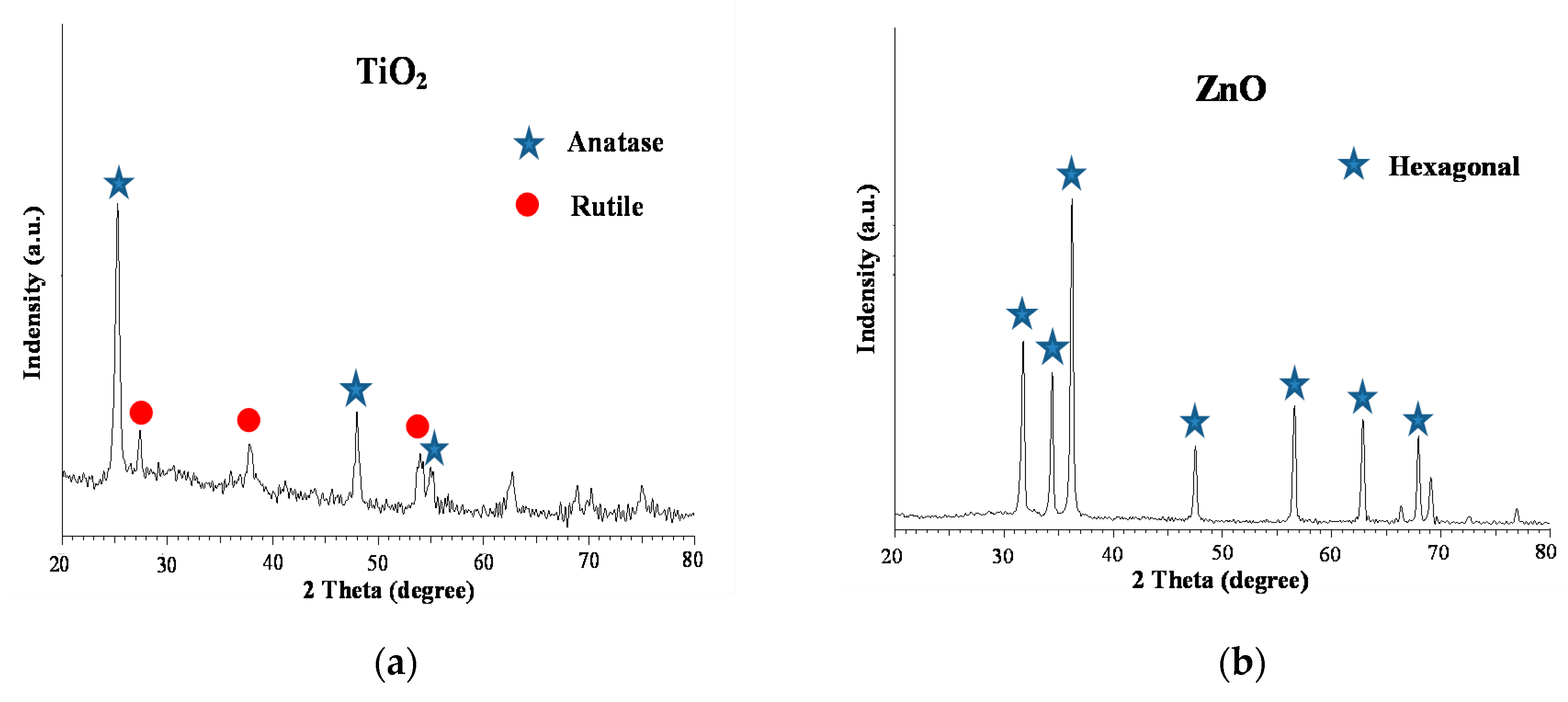
The surface of photocatalyst-coated POF was analyzed by a scanning electron microscopy (SEM) (Hitachi S-3000N, Tokyo, Japan) system. The TiO2 and ZnO nano-powders were used to analyze the absorption wavelength and the energy band gap of the photocatalyst by using a UV-VIS diffuse reflectance spectroscopy (DRS) (Hitachi U-3900, Tokyo, Japan). X-ray diffraction analysis (XRD) (Bruker, D8 Advance, Germany) can obtain the crystal structure of the material to be tested. An X-ray diffractometer was used in this study for identifying the crystal structure of the photocatalyst. The XRD pattern of TiO2 is shown in Figure 2a. Peaks of anatase appearing at 2θ: 25.4°, 48.2°, 55.2°, and the rutile at 2θ: 27.5°, 36.1° and 54.4° (morphology is 75% anatase and 25% rutile). The XRD pattern of the ZnO is shown in Figure 2b. The obtained spectrum has the ZnO main peaks at 2θ: 31.9°, 34.5°, 36.3°, 47.9°, 56.5°, 62.8° and 67.9° (morphology is hexagonal).
2.3. Kinetics and ROH,UV
Modified Langmuir-Hinshelwood (L-H) model was used to determine the rate of photocatalytic degradation of TCE and can be expressed as Equation (1) [18]. According to Equation (1), where kapp is the apparent degradation rate constant (min−1), C0 is the initial concentration of TCE (mg L−1), kr is the intrinsic reaction rate constant (mg L−1 min−1), and kS is the L-H adsorption constant (L mg−1).
The calculation of ROH,UV is by using Equation (2) [20]:
where H is the UV fluence (mJ cm−2), kOH,pCBA = 5.2 × 10⁹ M−1S−1, and t is the reaction time. The represents the total observed oxidation rate constant (cm2 mJ−1), which is based on fluence.
2.4. Experimental Parameters
Controlled experimental parameters are as follows. The TCE concentration was set to 1 mg L−1, which is based on the consideration of the actual concentration of TCE in the contaminated groundwater and refers to the previous study of TCE in photocatalytic treatment [21,22]. The treatment time was set at 1, 2, 3 and 4 h. The pH values used in the experiment were 4, 7 and 10. The types of nano-photocatalysts used were TiO2 and ZnO. The number of photocatalyst coating times was 1, 3, 5, 7 and 10. The treatment procedures included photolysis, TiO2-coated POF photocatalysis and ZnO-coated POF photocatalysis. The light intensity was 40 and 20 mW cm−2 for lamp A and lamp B, respectively. The initial concentration of pCBA was 0.05 μM. Experiments were conducted at pH 7 (except the study of the effect of pH) and the temperature was maintained at 25 °C. All experiments were repeated two times.
3. Results and Discussion
3.1. Thickness of Photocatalyst Layer with Different Coating Times
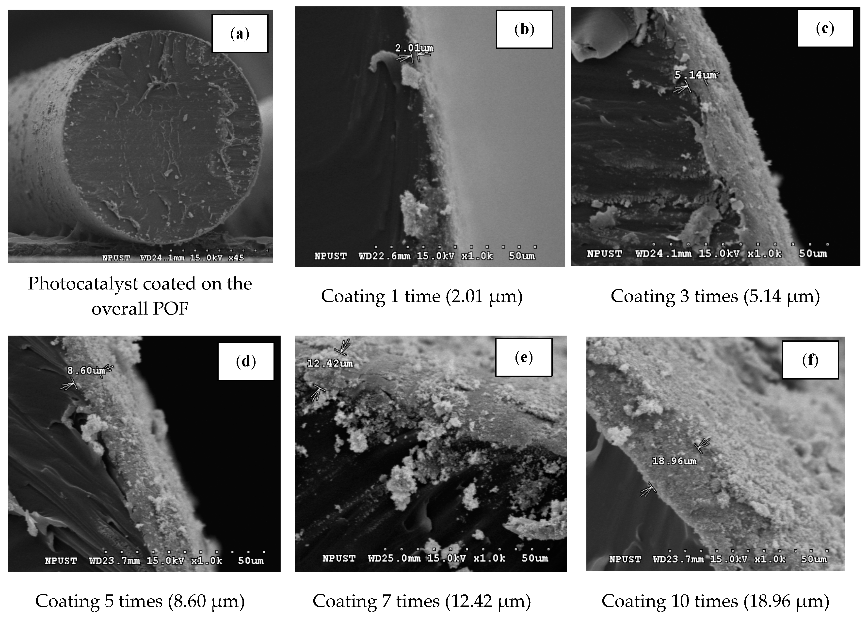
The thickness of the photocatalyst layer coated on the surface of an optical fiber was observed through a scanning electron microscope (SEM), as shown in Figure 3a, which shows the image of photocatalysts coated on a POF with the magnification of 45 times. In addition, the influence of the number of the coating was shown in Figure 3b–f as the coating times increased from 1 to 10, respectively, with the magnification of 1000 times. As can be seen, with the increase of the coating number from 1 to 10, the thickness of photocatalysts deposited on the surface of POF significantly increased from 2.01 to 18.96 μm. The thickness of photocatalysts deposited on the surface of POF was the average of three replicates by SEM. The thickness of the photocatalyst deposition can be calculated as: deposition thickness = 1.84 μm × coating times (±0.6 μm). The photocatalysts were evenly deposited on the POF surface by the dip-coating method. The average masses of coated photocatalysts on the optical fiber surface were 0.25, 0.70, 1.07, 1.47 and 1.87 mg for 1, 3, 5, 7 and 10 coating times, respectively.
3.2. Analysis of the Energy Gap of the Two Nano-Photocatalysts
The TiO2 and ZnO powders were used to analyze their absorption wavelength, and the energy band gap by DRS to evaluate their efficiency on photocatalyzation under light irradiation with different wavelengths. The absorption of intense light energy by photocatalysts results in the separation of electrons and the holes in them. Then, a chain reaction that generates •OH with strong oxidation potential occurs in order to help achieve an effective removal of pollutants. Yang et al. observed 0% and 99% removal of microcystin-LR by 6-h visible and 20-min UV light photocatalyzation, respectively [23]. Therefore, the wavelength of the absorbable energy of the photocatalyst is an important factor in the photocatalytic process.
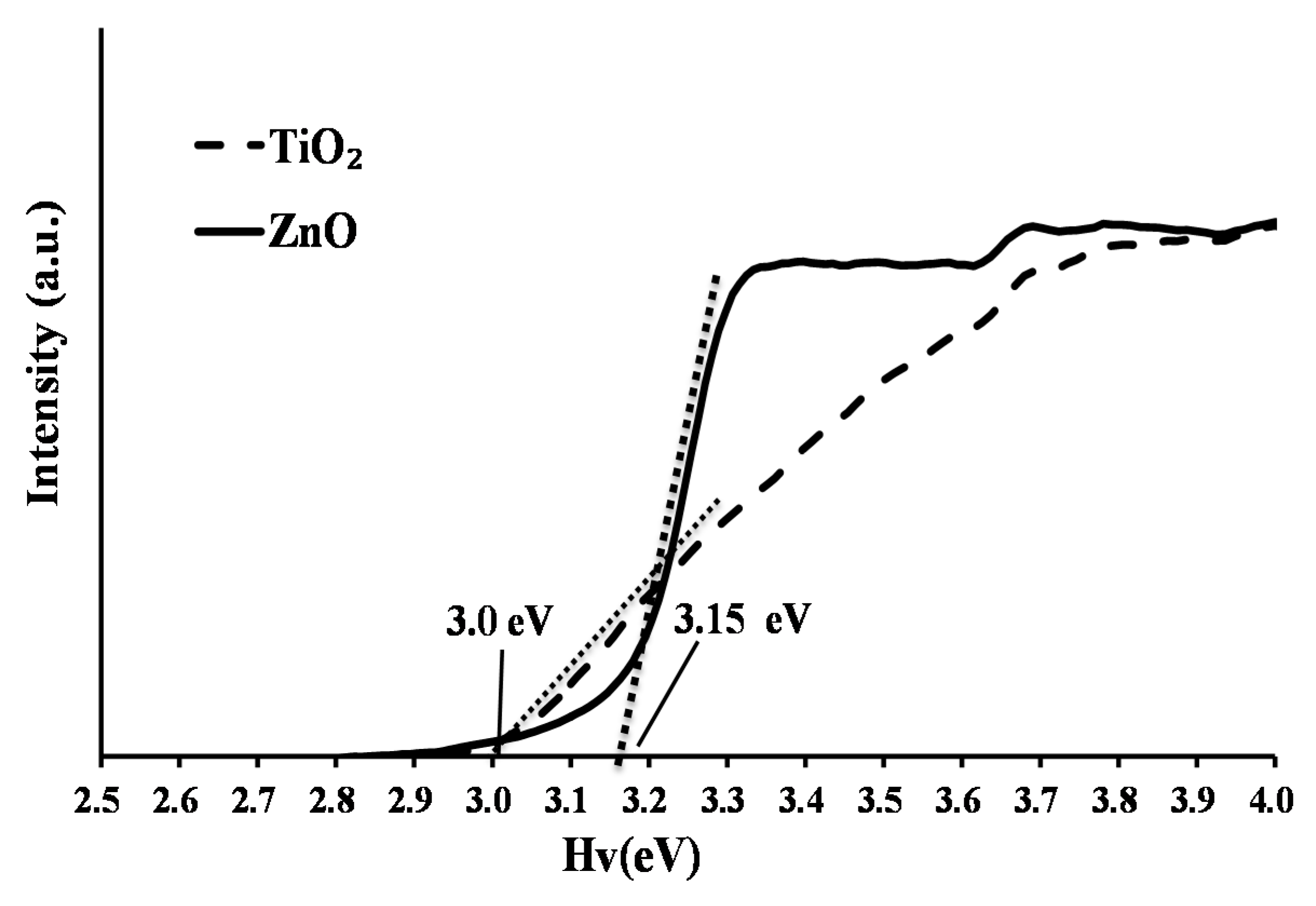
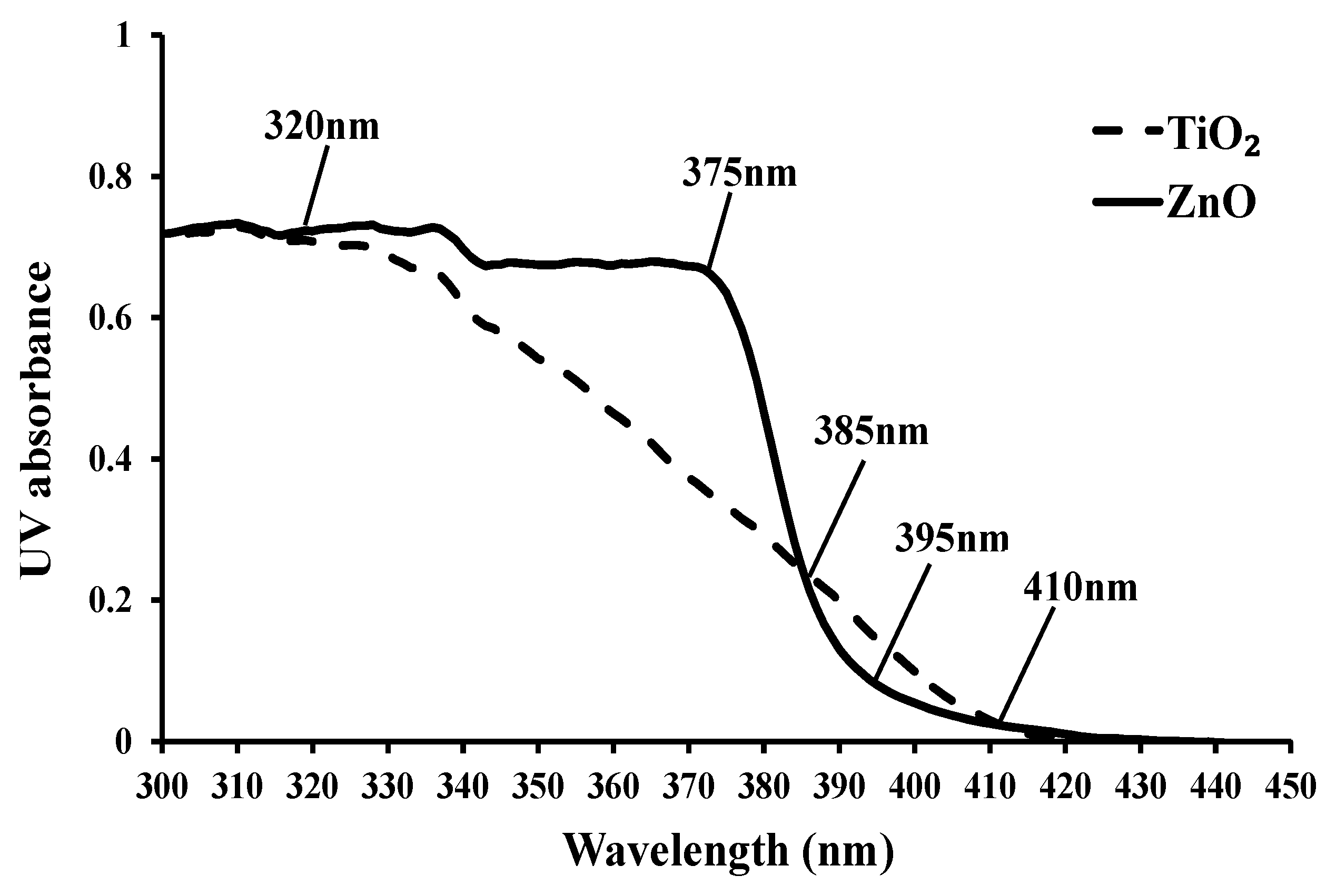
The energy gap of a photocatalyst can be calculated by using the equation: λ = 1240 Eg−1, where λ is the absorption wavelength (nm) and Eg is the energy gap (eV). Previous studies have shown that the band gap of TiO2 and ZnO is 3.0–3.2 eV and 3.2 eV, respectively [13,24,25]. The calculated energy gap of TiO2 and ZnO photocatalysts used in this study is 3.0 eV and 3.15 eV, respectively (Figure 4). In addition, according to Figure 5, significant changes of absorption by ZnO photocatalysts occurred between a wavelength of 375 nm and 410 nm, while in TiO2 the changes occurred between a wavelength of 320 nm and 410 nm. The ZnO photocatalyst is expected to perform higher photocatalytic efficiency than TiO2 between the wavelength of 320 nm and 385 nm, and the TiO2 outweighs ZnO between the wavelength of 385 nm and 410 nm. In this experiment, the light source wavelength of 395 nm for the TiO2 photocatalyst shows ease in the absorption of the light; the results of an experiment conducted by Han et al. showed the same measured results [26].
3.3. Effect of Coating Times on Photocatalytic Efficiency
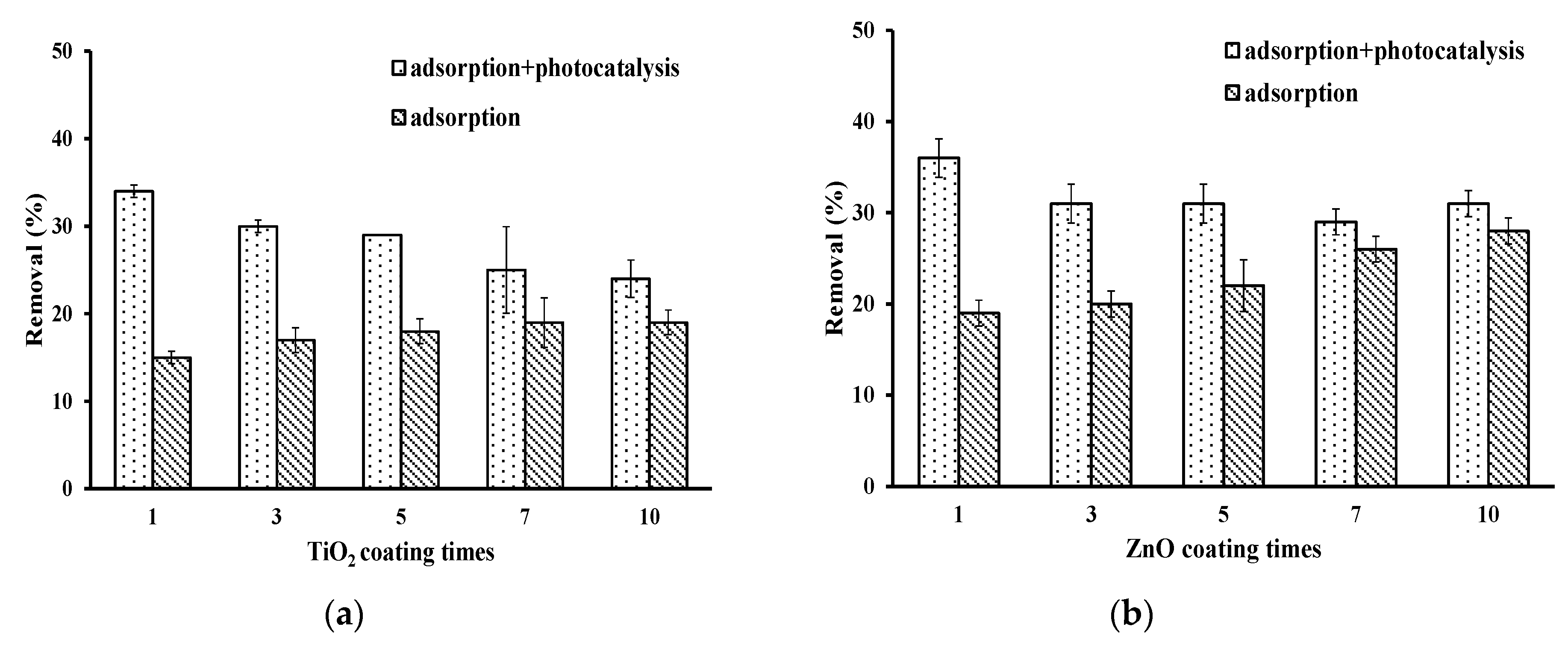
TiO2 and ZnO photocatalysts were coated on a single POF (2 mm in diameter) to study the effect of different coating times on the removal efficiency of TCE through adsorption (w/o light irradiation) and adsorption plus photocatalysis. The photocatalysts were coated on a single POF by 1, 3, 5, 7 and 10 times to treat the TCE solution for 2 h. As can be seen from Figure 6, the adsorption represents that the TCE was removed by photocatalyst adsorption without LED irradiation. The adsorption plus photocatalysis represents that the TCE was removed by adsorption and photocatalysis simultaneously. The adsorption plus photocatalysis of TCE with TiO2-coated POF resulted in the removal of 34%, 30%, 29%, 25% and 24% of TCE for the photocatalyst coated 1, 3, 5, 7 and 10 times, respectively. The adsorption only by the coated POF removed 15%, 17%, 18%, 19% and 19% of TCE. For ZnO photocatalysts, the adsorption plus photocatalysis removed 36%, 31%, 31%, 29% and 31% of TCE, and the adsorption only removed 19%, 20%, 22%, 26% and 28% of TCE. The TCE levels decreased with the formation of chloride which increased in the treated water for both coated photocatalysts after photocatalyzation by the proposed system. It was also found that more chloride formed in the TiO2-coated fiber system than that with the ZnO-coated fiber system (data not shown). The adsorption plus photocatalysis performed better than adsorption alone on TCE removal. It was also interesting to find that the removal efficiency of TCE by photocatalysis decreased with the increase of the coating times.
Joo et al. studied the photocatalytic treatment of TCE using a TiO2 catalyst as the carrier and fiber as the supporter [8]. A 1000 W xenon lamp was used in this study. They coated the optical fiber with TiO2 1, 3, 5 and 8 times. Their results show that the best removal efficiency of TCE was coating 3 times and the TCE was completely removed from the solution in 20 min. This result indicated that increasing the number of coating times also increased the amount of photocatalyst deposited on the fiber surface, which might block the light transmission from the fiber to the utmost photocatalysts. In addition, Farooq et al. used TiO2 photocatalysts to treat a solution containing TCE with a 15 W UVA lamp. Different amounts of photocatalyst (0.1, 0.3, 0.5, 0.7, 1.0 g) were added into the photoreactor [27]. Their experimental results show that the removal rate of TCE decreased from 55% to 18% when the TiO2 dosage was increased from 0.7 g to 1.0 g after 90 min of treatment time. This removal of TCE is mainly due to the excitation of the photocatalyst’s surface by the formation of electrons and holes in the presence of light. If the photocatalyst dosage is too high, it leads to a rapid combination of the electrons and holes that cause a decrease in the oxidation of pollutants. On the other hand, a chain reaction will lead to the formation of oxygen and •OH [28]. If excess photocatalyst is added, it causes the •OH to compete with each other, reducing the number of •OH and its probability of reacting with pollutants, and leads to poor removal efficiency. Without the presence of light irradiation, the adsorption effect increased with the increase of the number of coating times. This is due to the increase in the amount of photocatalyst on the POF surface which also increased the active position to adsorb more TCE.
3.4. Effect of Light Source on Photocatalytic Efficiency
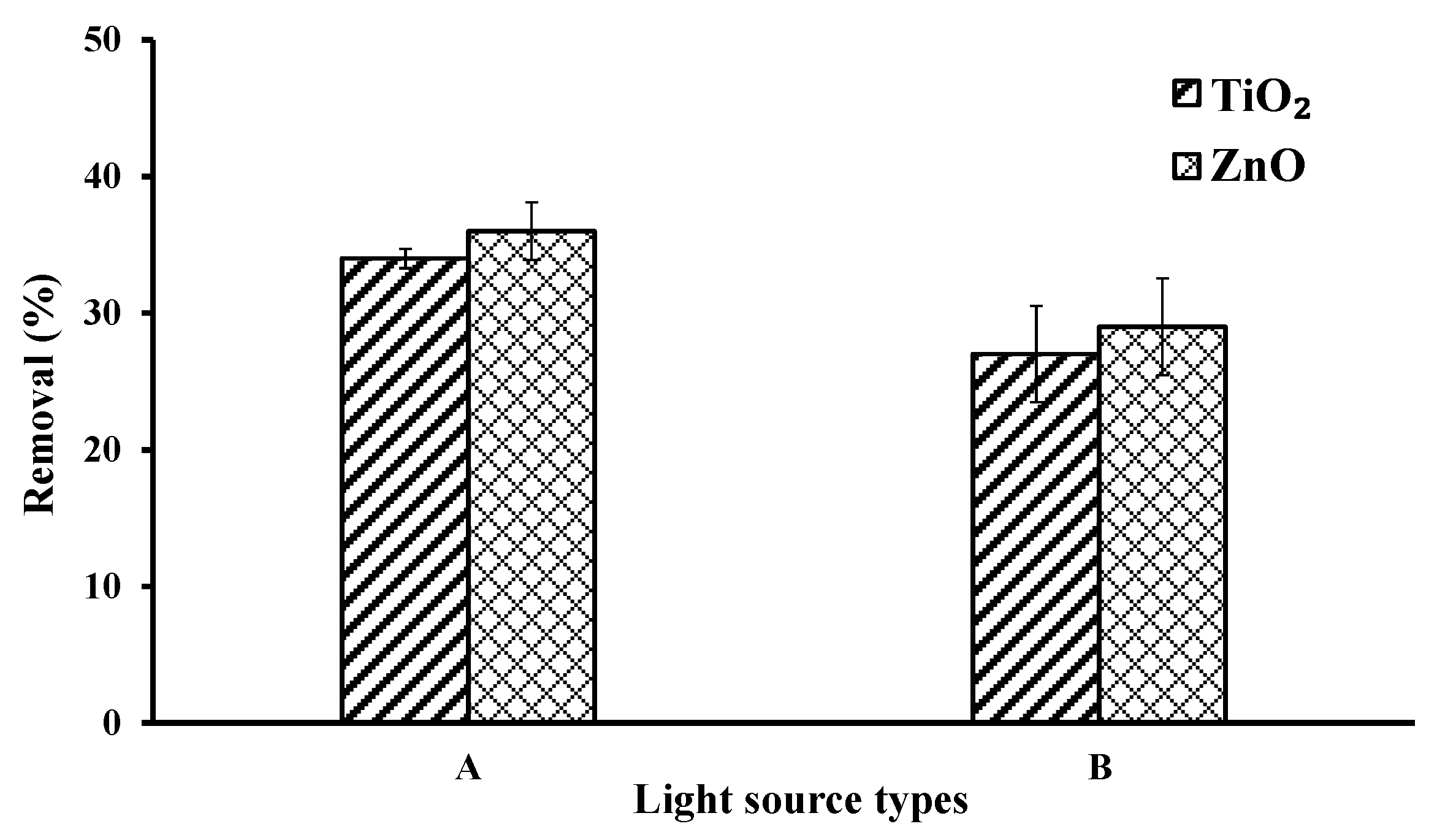
The lamp A (395 nm LED) and B (365 nm LED) both in the UVA wavelength were used to explore the effect of light source on the removal of TCE. The light intensity of lamp A and lamp B was 40 mW cm−2 and 20 mW cm−2, respectively. The results are shown in Figure 7. After 2 h of photocatalytic treatment, the removal efficiency of TCE by TiO2-coated POF with lamp A and lamp B was 34% and 27%, respectively. The removal efficiency of TCE by ZnO-coated POF with lamp A and lamp B was 36% and 29%, respectively. Using a higher light intensity LED lamp for photocatalysis can provide stronger energy to photocatalysts and form more •OH than the lower light intensity ones. Therefore, as can be seen from Figure 7, photocatalysis of TCE with lamp A obtained higher removal efficiency than with lamp B. This implies that light intensity is one of the main factors that affect photocatalytic removal of TCE. When the light intensity of the light source is increased, the efficiency of the photocatalytic treatment is improved. Jinyu et al. studied a similar light source in their experiments but changed its power to 100, 200 and 300 W, thereby increasing the light intensity of the light source. When Ag+/TiO2 powder was added into the treatment solution, the removal efficiency increased from 68% to 97%, with an increase in light power from 100 W to 300 W [29]. Based on the results, when strong light intensity is provided, photon energy can be increased and the photocatalysts can be excited and generate more electron-hole pairs, which increase the removal efficiency of the pollutants.
3.5. Effect of pH on Photocatalytic Efficiency
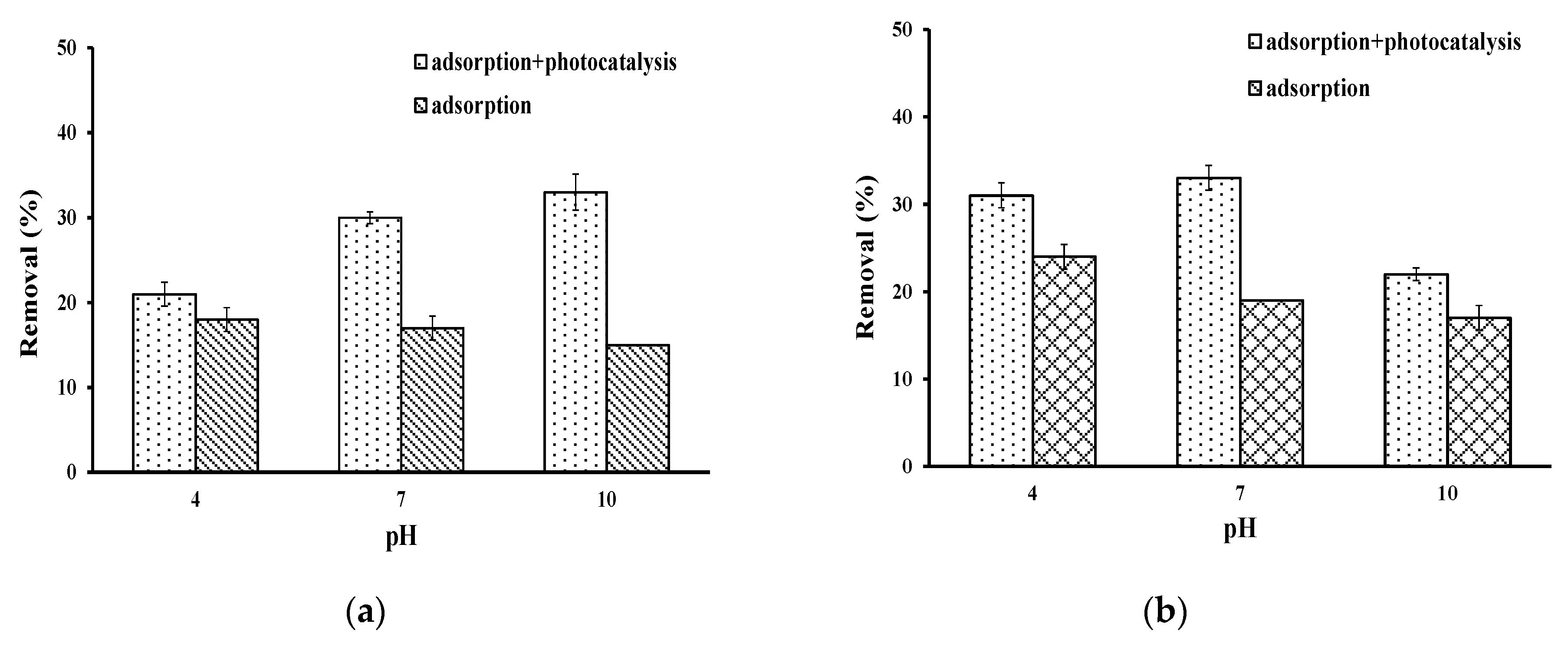
The TCE removal efficiency by adsorption plus photocatalysis under three different pH values were investigated under the same operating conditions. Lamp A was used as the light source for photocatalysis and the treatment time was 2 h. The POF adsorption efficiencies of TiO2-coated fiber without light irradiation were 18%, 17% and 15% for solution pH 4, 7 and 10, respectively, while the adsorption efficiencies for ZnO-coated POF were 24%, 19%, and 17%, respectively (Figure 8). In addition, the general catalyst adsorption mechanism can be divided into physical adsorption and chemical adsorption. The physical adsorption occurred on the photocatalyst’s surface and pores through van der Waals force, and the chemical adsorption is a chemical reaction between the adsorbate (pollutants) and the active site on the adsorbent (catalyst). The experimental results show that both TiO2- and ZnO-coated POF removed the least TCE by adsorption in basic pH. The the pH of point of zero charge (pHpzc) of tested TiO2 and ZnO photocatalysts were measured at 4.05 and 7.60, respectively. Therefore, the surface of both TiO2- and ZnO-coated optical fiber would be negatively charged when the pH of the solution was 10 [30,31]. Joo et al. indicated that the TCE is neutral and not dissociated through the whole of pH ranges. Therefore, the removal of TCE by adsorption was marginal [12].
In the adsorption plus photocatalysis process, the removal efficiency of TCE by TiO2-coated POF was 21%, 30%, and 33% at pH 4, 7 and 10, respectively. However, using ZnO-coated POF obtained removal efficiencies of TCE 31%, 33% and 22% at pH 4, 7 and 10, respectively (Figure 8). The results show that the removal efficiency of TiO2-coated POF increased with the increasing of pH value. This is mainly due to the pHpzc of TiO2 and ZnO which was 4.05 and 7.60, respectively. When the solution’s pH > pHpzc, the photocatalyst surface is negatively charged, coupled with the pH 10 solution containing more hydroxide ions (OH−). Chen et al. have pointed out that when the photocatalyst is excited by light energy, an increase in the removal of organic pollutants by the •OH can be observed, which increases the removal efficiency by photocatalysis [28]. On the TiO2 photocatalysts, the OH radicals produced in the solution react with the electron holes to initiate a chain reaction. However, due to the wavelength of LED (395 nm) and the energy gap of ZnO, it resulted in less formation of OH radicals by photocatalyzation with the ZnO-coated POF. This can be explained by the wavelength and the energy gap of absorbable light of the two photocatalysts used in this study. Figure 8 shows that TiO2 was more susceptible to the light source leading to an excitation of the electron-hole pairs; however, ZnO was not effectively excited by the light source, which led to poor photocatalytic efficiency. The photocatalytic efficiency of ZnO-coated POF on TCE decreased significantly at alkaline condition (pH 10). The TCE removal efficiency by ZnO-coated POF was better than that of TiO2-coated POF at pH 7. However, the primary removal mechanism of TCE by the two photocatalytic POFs was different because the adsorption efficiency of ZnO was better than that of TiO2. Nevertheless, the TiO2-coated POF outweighed the ZnO-coated POF on the formation of more hydroxyl radicals. More details are discussed in the Section 3.7.
3.6. Effect of Treatment Process on Photocatalytic Efficiency
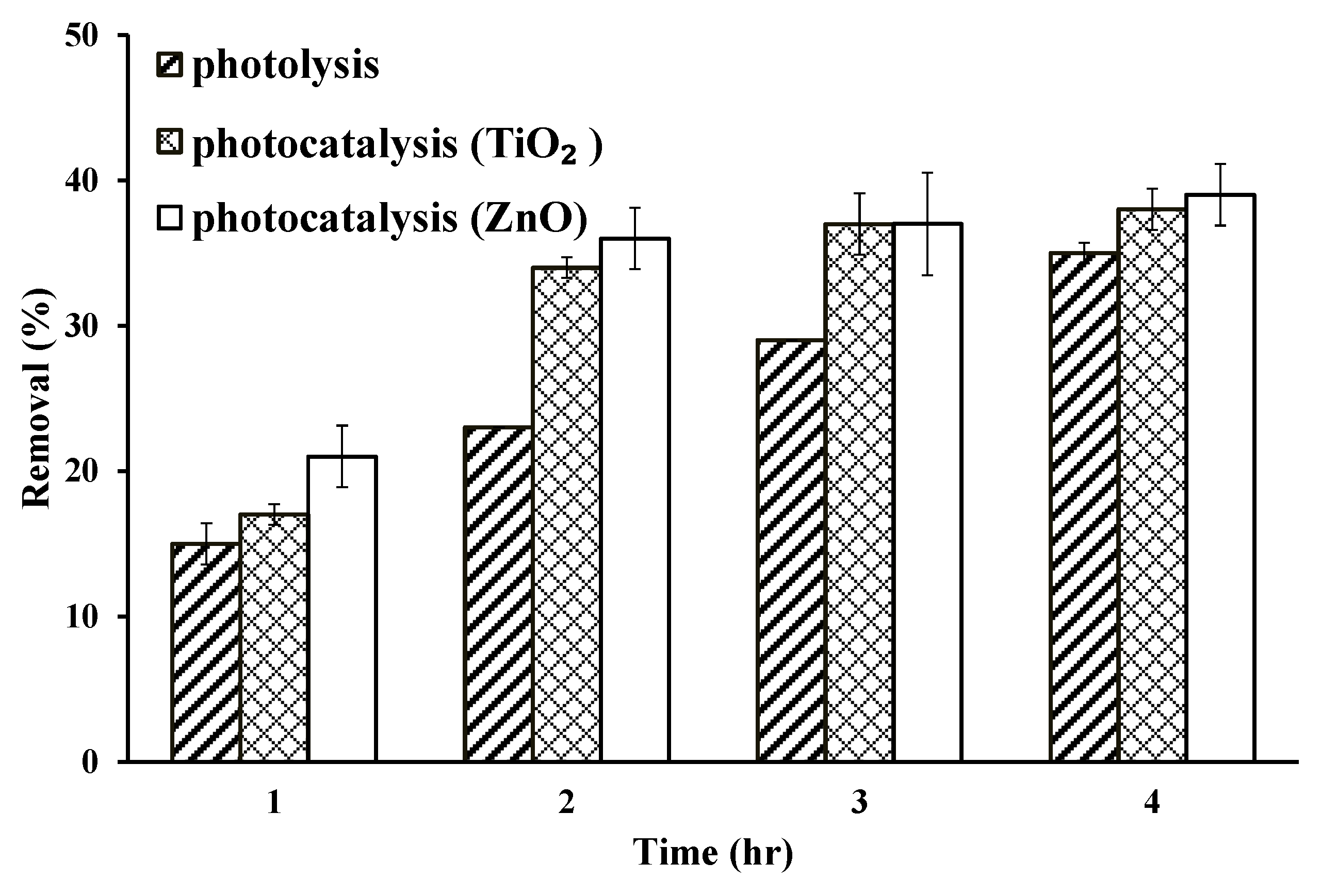
The lamp A with a light intensity of 40 mW cm−2 and a wavelength of 395 nm was used to illuminate the photocatalyst-coated POF. The results are shown in Figure 9, which shows the removal efficiency by photolysis, TiO2-coated POF photocatalysis and ZnO-coated POF photocatalysis. When conducting photolysis, the POF was used without coating any photocatalysts. As can be seen from Figure 9, 15%, 23%, 29% and 35% of TCE were removed after 1, 2, 3 and 4 h of photolysis, respectively. Using TiO2-coated POF in photocatalysis achieved 17%, 34%, 37% and 38% of TCE removal, while the ZnO-coated POF achieved 21%, 36%, 37% and 39%, respectively. It is obvious that POF coated with photocatalysts enhanced the degradation of TCE compared with the photolysis process. In addition, the increase of the treatment time also effectively improved the removal efficiency of TCE. However, the differences in TCE removal percentages were getting smaller as the treatment time increased. When the photocatalyst was excited, the active positions for generating electron-hole pairs may be gradually reduced. On the other hand, the active sites on the photocatalysts may be gradually filled by adsorbed contaminants resulting in a decrease in removal efficiency. Joo et al. used nanoscale ZnO with four UVC lamps to photocatalytically degrade TCE contaminants in aqueous solution for 60 min [12]. Their results showed that about 70% of the TCE was degraded after 30 min of the experiment and was about 95% at the 60 min mark. This indicates that the removal efficiency gradually decreased, although the treatment time was prolonged.
3.7. Formation of Hydroxyl Radicals During Photocatalytic Process
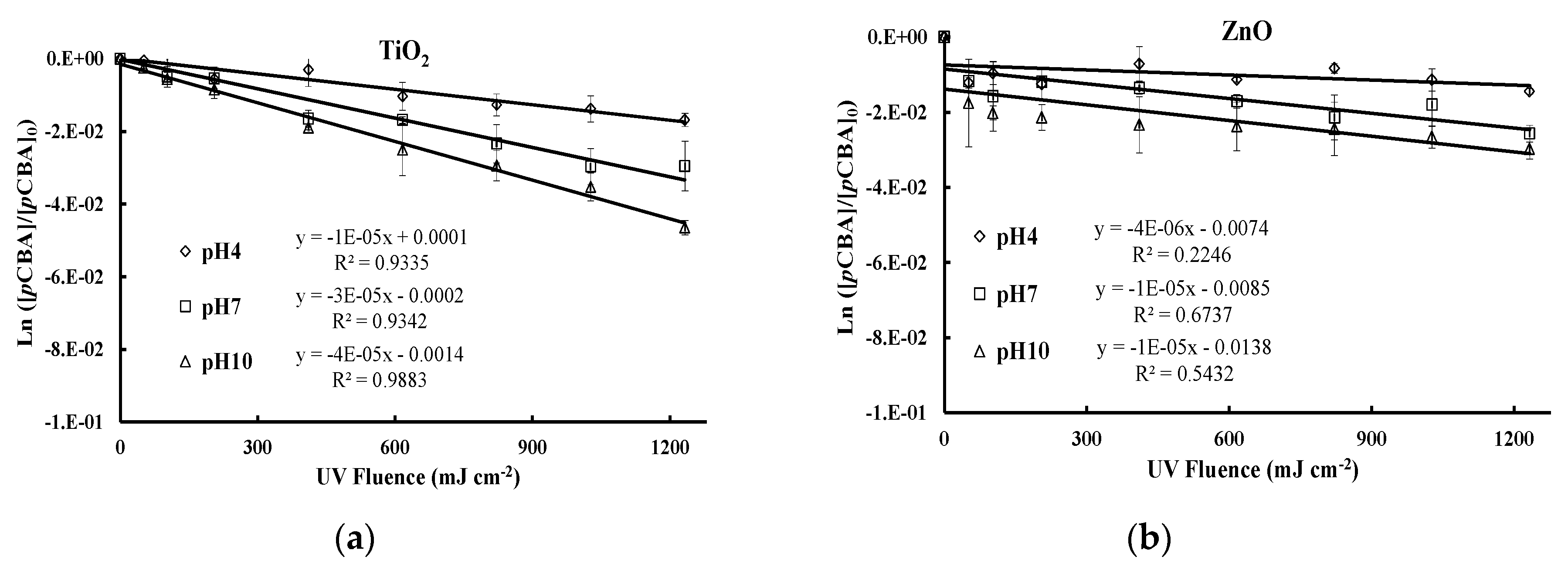
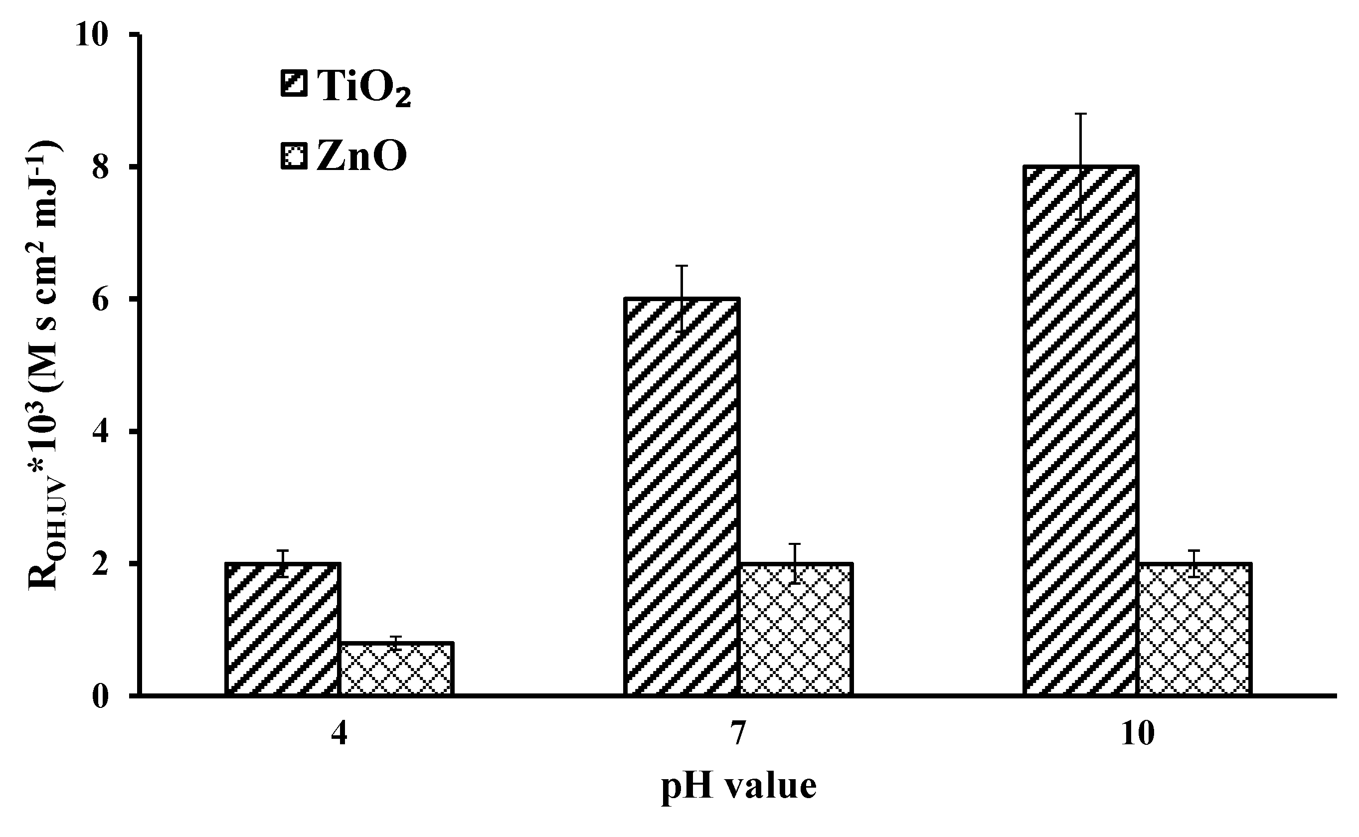
The •OH conversion rate (ROH,UV) of the photocatalytic process by two photocatalyst-coated POFs was investigated. The ROH,UV was estimated according to Rosenfeldt and Linden [20]. The light intensity of the optical fiber is calculated by taking a single fiber with length of 16 cm and using a UVA meter to measure its light intensity every 2 cm. Then, the calculated average light intensity was 0.17 mW cm−2 and multiplying it by time in seconds, which obtained the luminous flux (H) (mJ cm−2). Based on the results presented in Figure 10, kOH is obtained by dividing the reaction rate of the •OH and pCBA by k•OH, pCBA = 5.2 × 10⁹ M−1 S−1. The k values of TiO2 at pH values of 4, 7, and 10 were 0.1 × 10⁻⁵, 0.3 × 10⁻⁵ and 0.4 × 10⁻⁵, respectively, and for ZnO were 0.4 × 10⁻⁶, 0.1 × 10⁻⁵, and 0.1 × 10⁻⁵, respectively. The calculated concentrations of •OH were presented in Figure 11. It can be seen that the ROH,UV of the TiO2-coated POF at pH 4, 7 and 10 were 2 × 10³, 6 × 10³, and 8 × 10³ M s cm2 mJ−1, respectively; while the ZnO-coated POF was 8 × 10², 2 × 10³, and 2 × 10³ M s cm2 mJ−1, respectively. In acidic solution, the H+ is present on the photocatalyst’s surface and in the solution. Thus, increasing the pH value increases the TiO2 hydroxyl radical conversion efficiency, which indicates that the TiO2 photocatalyst is excited by the light source. On the other hand, the rates of ZnO photocatalytic reaction under pH conditions of 4, 7, and 10 were lower than that of TiO2, and its photocatalytic reaction rate also increased with the increasing of pH value. Since the photocatalytic conversion efficiency of the ZnO-coated POF was not that high, therefore, the primary removal mechanism of the ZnO-coated POF, compared with the TiO2-coated POF, is not the generation of hydroxyl radicals, but may be carried out by photocatalytic degradation of TCE through photocatalyst adsorption. Pozan et al. also found that the adsorption of TCE by ZnO photocatalysts was better than TiO2 [13]. Moreover, Hashimoto et al. indicated that the anatase phase in TiO2 significantly contributes to photocatalyzation, but the hexagonal phase in ZnO does not benefit it [32]. The XRD analysis in Section 2.2 also shows that the main crystal phase of the TiO2 is anatase.
4. Conclusions
The photocatalytic reaction was carried out by using LED with coated POF to remove TCE in water. The effects of photocatalyst coating times, light intensity, solution pH, and treatment process on the removal of TCE were investigated, and the formation of hydroxyl radicals of the proposed system was estimated. The photocatalytic efficiency of the photocatalyst-coated POF decreased with the increase in the number of coating times. However, the removal of TCE through photocatalyst adsorption increased as the coating times increased. Under the irradiation of LED-UVA, enhancing the light intensity increases the photocatalytic efficiency of TCE by coated POF with either photocatalyst. The photocatalytic efficiency can be further increased by increasing the treatment time. The energy gap of TiO2 and ZnO photocatalysts was 3.0 eV and 3.15 eV, respectively, and the photocatalytic efficiency of the TiO2 photocatalyst was enhanced by increasing the pH of TCE solutions. The ZnO-coated POF film is inferior to that of the TiO2-coated POF under alkaline conditions, since the mechanism of TCE removal by ZnO is adsorption, while the TiO2‘s primary mechanism is photocatalysis. The absorption wavelength of photocatalysts measured by DRS indicates that ZnO, compared to TiO2, at 395 nm wavelength cannot absorb light efficiently, thus, being less susceptible to excitation by the experimental light source. The ROH,UV of the photocatalyst-coated POF increases with an increasing pH value of the solution. The value of ROH,UV for TiO2 was higher than for ZnO which suggested that a TiO2-coated POF is more suitable than a ZnO-coated POF in degrading TCE. According to our experimental results, the high removal efficiency of TCE would be achieved by using the light source of 395 nm LED, with a one-time coating of the TiO2 photocatalyst in the pH 10 solution.
Author Contributions
Conceptualization: K.-C.C.; methodology: K.-C.C.; investigation: C.-J.C., C.-C.W., L.-T.H. and K.-C.C.; resources: K.-C.C.; data curation: C.-J.C.; writing—original draft preparation: C.-J.C.; writing—review and editing: C.-C.W., L.-T.H. and K.-C.C.; supervision: K.-C.C.; project administration: K.-C.C.; funding acquisition: K.-C.C.
Funding
This research was funded by the Environmental Protection Administration of Taiwan.
Conflicts of Interest
The authors declare no conflicts of interest.
References
- Caliman, F.A.; Robu, B.M.; Smaranda, C.; Pavel, V.L.; Gavrilescu, M. Soil and groundwater cleanup: Benefits and limits of emerging technologies. Clean Technol. Environ. Polic. 2011, 13, 241–268. [Google Scholar] [CrossRef]
- Nguyen, T.-V.; Wu, J.C.S. Photoreduction of CO2 in an optical-fiber photoreactor: Effects of metals addition and catalyst carrier. Appl. Catal. A-Gen. 2008, 335, 112–120. [Google Scholar] [CrossRef]
- Ma, C.M.; Ku, Y.; Wang, W.; Jeng, F.T. A new optical fiber reactor for the photocatalytic degradation of gaseous organic contaminants. React. Kinet. Catal. Lett. 2008, 94, 199–206. [Google Scholar] [CrossRef]
- Wu, J.C.S.; Wu, T.-H.; Chu, T.; Huang, H.; Tsai, D. Application of optical-fiber photoreactor for CO2 photocatalytic reduction. Top. Catal. 2008, 47, 131–136. [Google Scholar] [CrossRef]
- Wang, Z.-Y.; Chou, H.-C.; Wu, J.C.S.; Tsai, D.P.; Mul, G. CO2 photoreduction using NiO/InTaO4 in optical-fiber reactor for renewable energy. Appl. Catal. A-Gen. 2010, 380, 172–177. [Google Scholar] [CrossRef]
- Athanasiou, D.A.; Romanos, G.E.m.; Falaras, P. Design and optimization of a photocatalytic reator for water purification combining optical fiber and membrane technologies. Chem. Eng. J. 2016, 305, 92–103. [Google Scholar] [CrossRef]
- Barton, I.; Matejec, V.; Matousek, J. Photocatalytic activity of nanostructured TiO2 coating on glass slides and optical fibers for methylene blue or methyl orange decomposition under different light excitation. J. Photochem. Photobiol. A Chem. 2016, 317, 72–80. [Google Scholar] [CrossRef]
- Joo, H.; Jeong, H.; Jeon, M.; Moon, I. The use of plastic optical fibers in photocatalysis of trichloroethylene. Sol. Energy Mater. Sol. Cells 2003, 79, 93–101. [Google Scholar] [CrossRef]
- Kim, S.; Kim, M.; Lim, S.K.; Park, Y. Titania-coated plastic optical fiber fabrics for remote photocatalytic degradation of aqueous pollutants. J. Environ. Chem. Eng. 2017, 5, 1899–1905. [Google Scholar] [CrossRef]
- Zhong, N.; Chen, M.; Luo, Y.; Wang, Z.; Xin, X.; Rittmann, B.E. A novel photocatalytic optical hollow-fiber with high photocatalytic activity for enhancement of 4-chlorophenol degradation. Chem. Eng. J. 2019, 355, 731–739. [Google Scholar] [CrossRef]
- Tugaoen, H.O.; Segura, S.G.; Hristovski, K.; Westerhoff, P. Compact light-emitting diode optical fiber immobilized TiO2 reactor for photocatalytic water treatment. Sci. Total Environ. 2018, 613–614, 1331–1338. [Google Scholar] [CrossRef] [PubMed]
- Joo, J.C.; Ahn, C.H.; Jang, D.G.; Yoon, Y.H.; Kim, J.K.; Campos, L.; Ahn, H. Photocatalytic degradation of trichloroethylene in aqueous phase using nano-ZnO/Laponite composites. J. Hazard. Mater. 2013, 263, 569–574. [Google Scholar] [CrossRef] [PubMed]
- Pozan, G.S.; Kambur, A. Significant enhancement of photocatalytic activity over bifunctional ZnO–TiO2 catalysts for 4-chlorophenol degradation. Chemosphere 2014, 105, 152–159. [Google Scholar] [CrossRef] [PubMed]
- Lee, K.M.; Lai, C.W.; Ngai, K.S.; Juan, J.C. Recent developments of zinc oxide based photocatalyst in water treatment technology: A review. Water Res. 2016, 88, 428–448. [Google Scholar] [CrossRef] [PubMed]
- Hernández-Alonso, M.D.; Fresno, F.; Suárez, S.; Coronado, J.M. Development of alternative photocatalysts to TiO2: Challenges and opportunities. Energy Environ. Sci. 2009, 2, 1231–1257. [Google Scholar] [CrossRef]
- Serrà, A.; Zhang, Y.; Sepùlveda, B.; Gómez, E.; Nogués, J.; Michler, J.; Philippe, L. Highly active ZnO-based biomimetic fern-like microleaves for photocatalytic water decontamination using sunlight. Appl. Catal. B Environ. 2019, 248, 129–146. [Google Scholar] [CrossRef]
- Sanchez, C.; Arribart, H.; Guille MM, G. Biomimetism and bioinspiration as tools for the design of innovative materials and systems. Nat. Mater. 2005, 4, 277–288. [Google Scholar] [CrossRef]
- Elovitz, M.S.; von Gunten, U. Hydroxyl radical ozone ratios during ozonation processes. I-The R-ct concept. Ozone-Sci. Eng. 1999, 21, 239–260. [Google Scholar] [CrossRef]
- Jung, H.Y.; Choi, H.C. Catalytic decomposition of ozone and para-Chlorobenzoic acid (pCBA) in the presence of nanosized ZnO. Appl. Catal. B-Environ. 2006, 66, 288–294. [Google Scholar] [CrossRef]
- Rosenfeldt, E.J.; Linden, K.G. The ROH,UV Concept to Characterize and the Model UV/H2O2 Process in Natural Waters. Environ. Sci. Technol. 2007, 41, 2548–2553. [Google Scholar] [CrossRef]
- Arconada, N.; Duran, A.; Suarez, S.; Portela, R.; Coronado, J.M.; Sanchez, B.; Castro, Y. Synthesis and photocatalytic properties of dense and porous TiO2-anatase thin films prepared by sol-gel. Appl. Catal. B-Environ. 2009, 86, 1–7. [Google Scholar] [CrossRef]
- Nishikiori, H.; Tagahara, M.; Mukoyama, L.; Fujii, T. Photocatalytic degradation of dichloroacetyl chloride adsorbed on TiO2. Res. Chem. Intermed. 2010, 36, 947–957. [Google Scholar] [CrossRef]
- Yang, L.; Yu, L.E.; Ray, M.B. Degradation of paracetamol in aqueous solution by TiO2 photocatalysis. Water Res. 2008, 42, 3480–3488. [Google Scholar] [CrossRef] [PubMed]
- Mohapatra, D.P.; Brar, S.K.; Daghrir, R.; Tyagi, R.D.; Picard, P.; Surampalli, R.Y.; Drogui, P. Photocatalytic degradation of carbamazepine in wastewater by using a new class of whey-stabilized nanocrystalline TiO2 and ZnO. Sci. Total Environ. 2014, 485–486, 263–269. [Google Scholar] [CrossRef] [PubMed]
- Xiao, S.; Zhao, L.; Leng, X.; Lang, X.; Lian, J. Synthesis of amorphous TiO2 modified ZnO nanorod film with enhanced photocatalytic properties. Appl. Surf. Sci. 2014, 299, 97–104. [Google Scholar] [CrossRef]
- Han, J.; Liu, Y.; Singhal, N.; Wang, L.; Gao, W. Comparative photocatalytic degradation of estrone in water by ZnO and TiO2 under artificial UVA and solar irradiation. Chem. Eng. J. 2012, 213, 150–162. [Google Scholar] [CrossRef]
- Farooq, M.; Raja, I.A.; Pervez, A. Photocatalytic degradation of TCE in water using TiO2 catalyst. Sol. Energy 2009, 83, 1527–1533. [Google Scholar] [CrossRef]
- Chen, K.-C.; Wang, Y.-H.; Lu, Y.-C. Treatment of polluted water for reclamation using photocatalysis and constructed wetlands. Catal. Today 2011, 175, 276–282. [Google Scholar] [CrossRef]
- Jinyu, C.; Lei, Z. Photocatalytic Degradation of Methylene Blue with Side-glowing Optical Fiber Deliverying Visible Light. Chin. J. Chem. Eng. 2012, 20, 895–899. [Google Scholar]
- Bahnemann, W.; Muneer, M.; Haque, M.M. Titanium dioxide-mediated photocatalysed degradation of few selected organic pollutants in aqueous suspensions. Catal. Today 2007, 124, 133–148. [Google Scholar] [CrossRef]
- Kanel, S.R.; Al-Abed, S.R. Influence of pH on the transport of nanoscale zinc oxide in saturated porous media. J. Nanoparticle Res. 2011, 13, 4035–4047. [Google Scholar] [CrossRef]
- Hashimoto, K.; Wasada, K.; Osaki, M.; Shono, E.; Adachi, K.; Toukai, N.; Kera, Y. Photocatalytic oxidation of nitrogen oxides over titania-zeolite composite catalyst to remove nitrogen oxides in the atmosphere. Appl. Catal. B Environ. 2001, 30, 429–436. [Google Scholar] [CrossRef]
Figure 1.
Schematic diagram of plastic optical fiber (POF) structure and LED and coated POF.

Figure 2.
XRD patterns for catalysts. (a) TiO2 and (b) ZnO.

Figure 3.
The effect of photocatalyst coating times on the thickness of photocatalyst layer on the POF surface.
Figure 3.
The effect of photocatalyst coating times on the thickness of photocatalyst layer on the POF surface.

Figure 4.
Energy gap estimation for TiO2 and ZnO photocatalysts.

Figure 5.
UV-VIS DRS of TiO2 and ZnO photocatalysts.

Figure 6.
Effect of the number of coating times on TCE removal (a) TiO2 and (b) ZnO.

Figure 7.
Effect of light source on TCE removal. (Lamp A: 395 nm LED, light intensity: 40 mW cm−2; Lamp B: 365 nm LED, light intensity: 20 mW cm−2).
Figure 7.
Effect of light source on TCE removal. (Lamp A: 395 nm LED, light intensity: 40 mW cm−2; Lamp B: 365 nm LED, light intensity: 20 mW cm−2).

Figure 8.
Effect of solution pH on photocatalytic degradation of TCE by coating (a) TiO2 and (b) ZnO on POF.
Figure 8.
Effect of solution pH on photocatalytic degradation of TCE by coating (a) TiO2 and (b) ZnO on POF.

Figure 9.
Effect of treatment process on TCE removal.

Figure 10.
Effect of luminous flux on photocatalytic degradation of pCBA by coating (a) TiO2 and (b) ZnO on POF.
Figure 10.
Effect of luminous flux on photocatalytic degradation of pCBA by coating (a) TiO2 and (b) ZnO on POF.

Figure 11.
Effect of pH on hydroxyl radical conversion rate.

© 2019 by the authors. Licensee MDPI, Basel, Switzerland. This article is an open access article distributed under the terms and conditions of the Creative Commons Attribution (CC BY) license (http://creativecommons.org/licenses/by/4.0/).
Share and Cite
MDPI and ACS Style
Chen, C.-J.; Wu, C.-C.; Hsieh, L.-T.; Chen, K.-C. Treatment of Trichloroethylene with Photocatalyst-Coated Optical Fiber. Water 2019, 11, 2391. https://doi.org/10.3390/w11112391
AMA Style
Chen C-J, Wu C-C, Hsieh L-T, Chen K-C. Treatment of Trichloroethylene with Photocatalyst-Coated Optical Fiber. Water. 2019; 11(11):2391. https://doi.org/10.3390/w11112391
Chicago/Turabian StyleChen, Ching-Jung, Chih-Chao Wu, Lien-Te Hsieh, and Kuan-Chung Chen. 2019. "Treatment of Trichloroethylene with Photocatalyst-Coated Optical Fiber" Water 11, no. 11: 2391. https://doi.org/10.3390/w11112391
Note that from the first issue of 2016, this journal uses article numbers instead of page numbers. See further details here.